Those of you who have been following me for a while now have probably noticed that I like data. I prefer to measure, analysis, and calculate, rather than just guessing at things. What can I say, it's an engineer thing!
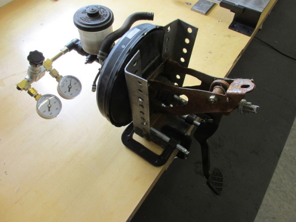
With that in mind, an adjustable brake proportioning valve has been on my list of things to add for a while now, but the usual tuning method of "guess and check" didn't really appeal to me. So, I built this simple (and yes, ugly) test rig to map the function of a Wilwood adjustable proportioning valve. I have done the math to figure out what proportioning valve slope and knee point would be optimal for my brake setup, but that math isn't too useful without knowing for sure what the valve is actually doing!
Two 1000psi pressure gauges, a few plumbing fittings, the proportioning valve to be tested, and an old master cylinder / brake pedal. By applying pressure to the pedal with my knee and watching the gauges I can easily measure the effects of the proportioning valve at various settings. In that way, I generated the data shown in the chart below:
| Wilwood Proportioning Valve Test Data |
||
| # of Turns | PSI In | PSI Out |
| 0 | 200 | 120 |
| 400 | 260 | |
| 600 | 360 | |
| 800 | 460 | |
| 1 | 400 | 320 |
| 600 | 420 | |
| 800 | 520 | |
| 2 | 400 | 380 |
| 600 | 480 | |
| 800 | 580 | |
| 3 | 600 | 540 |
| 800 | 640 | |
| 4 | 600 | 600 |
| 800 | 700 | |
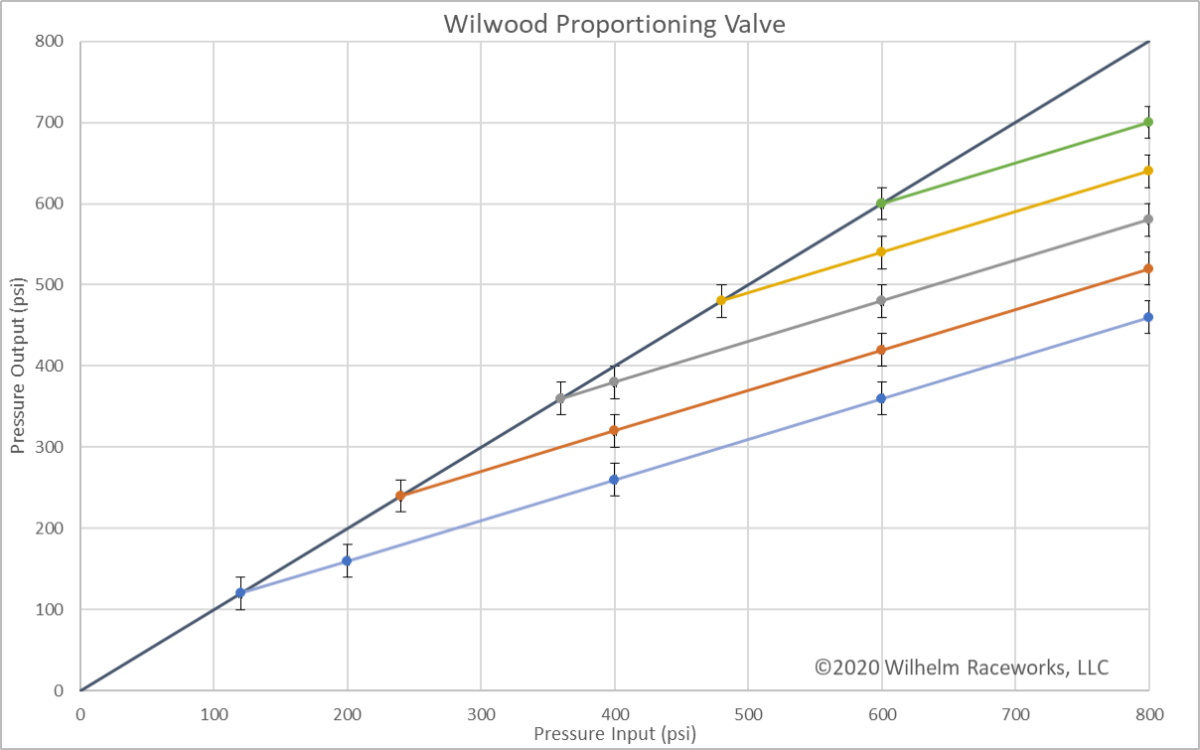
Graphing the data (and extending it to intercept the diagonal line) produces the graph below.
Finally, the chart below shows the calculated slope and knee point for each of the first 5 adjustment points (0 turns through 4 turns). The valve actually has a little over 10 turns of adjustment, but it is difficult to produce over 800psi on my test rig, so I only tested the first 4.
| Wilwood Proportioning Valve | ||
| # Turns | Knee Point | Slope |
| 0 | 120 | .50 |
| 1 | 240 | .50 |
| 2 | 360 | .50 |
| 3 | 480 | .50 |
| 4 | 600 | .50 |
Those values can then be plugged into the calculator found at the end of my Brake Bias article. For my setup, two turns would appear to produce near perfect bias, so that is where I will start. Fine tuning on the car may still be beneficial, but at least I know I have a good starting point, and I know how much effect a given adjustment will have.
Since this article was originally published I have tested an additional valve and re-tested my own valve, and averaged the numbers to produce the charts above. The two valves varied in their output by 40psi, represented by the error bars on the graph. I urge some caution when using this data to set your own valve. Start maybe one turn less than you think will be optimal, and adjust from there!
And here it is installed in the car, using the stock proportioning valve bracket from an ABS brake system, and a combination of ABS and non-ABS plumbing. The valve I used is Wilwood part number 260-8419. I used 1/8npt to M10 inverted flare adapters from Technafit, to adapt from the valve to the stock brake lines and a T fitting from an MR2 stock rear brake line. One warning on plumbing these, most of the MR2 brake lines have extended unthreaded noses on the tube nuts and won't fit any commercially available adapters or T fittings.
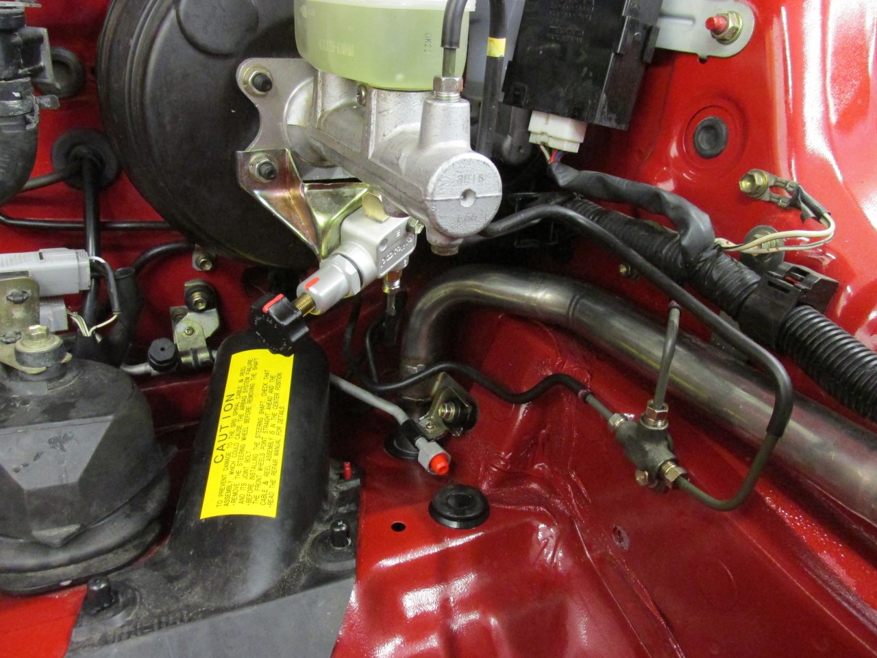
I now offer a bolt in installation kit for the Wilwood proportioning valve. This makes for a much easier install than dealing with the stock hard lines like I did originally.