For years I have wanted to use strain gauges to directly measure the forces on suspension components on my car. But every search for the hardware to do so dead ended into laboratory grade items, with a laboratory grade price to match. So I made do with what I felt were high estimates of the loads that various parts would see and designed around those. Finally last year I stumbled onto the pieces I needed at a reasonable price!
I am writing this article for two reasons. One of course is to share some of the lengths I go to to make my parts the best they can be. But the other, and really the bigger reason, is when I went searching for this sort of data myself I found very little of it on the internet, and also very little information on how the average person might acquire the data for themselves. If you find this even though you aren't an MR2 person but were looking for this sort of information for some other project, this article is for you! Send me an email to say hello, or better yet check out the Frankenstein Motorworks Discord server. It's a great community with a lot of technically minded people, and many of them are also working on cars that are not MR2s.
The Strain Gauge Setup
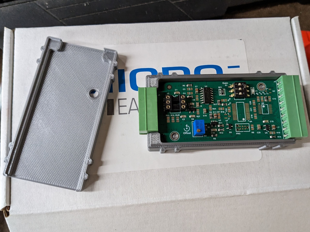
I won't go into detail on what strain gauges are or how they work, there are many good resources for that on the internet. But in short, a strain gauge measures strain (change in length / unit of length) by measuring change in the resistance of an electrical circuit. From the strain data, the force that produced that strain can be calculated provided the geometry and material of the part being measured are well known. The problem is, the changes in resistance are tiny, so a very precise amplifier is needed to produce a voltage signal that is able to be measured. This is the point that often gets quite expensive. The piece that made this relatively affordable was the Tacuna Systems Load Cell Amplifier. I purchased the $100 manual version without the enclosure (I 3D printed my own) and no other special options. The amplifier came with all of the calibration data on a sticker on the circuit board. Handy!
I designed and 3D printed my own enclosure for the amp. Two halves that nest together and close with zip ties with a hole to access the manual zero point adjustment screw.
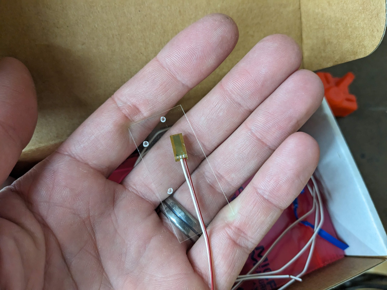
I purchased a 10 pack of strain gauges from Micro-Measurements.com, part number C4A-13-235SLA-350-23P. Decoding the strain gauge part number and deciding which ones to use took a little while to figure out and the data sheets don't exactly make it clear, but the Micro-Measurements website was a great resource to figure it all out. I highly recommend digging into their blog and other technical articles and calculators if you wish to do your own strain measurements.
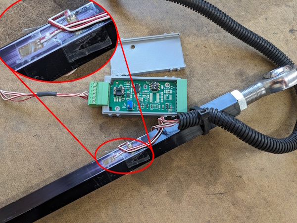
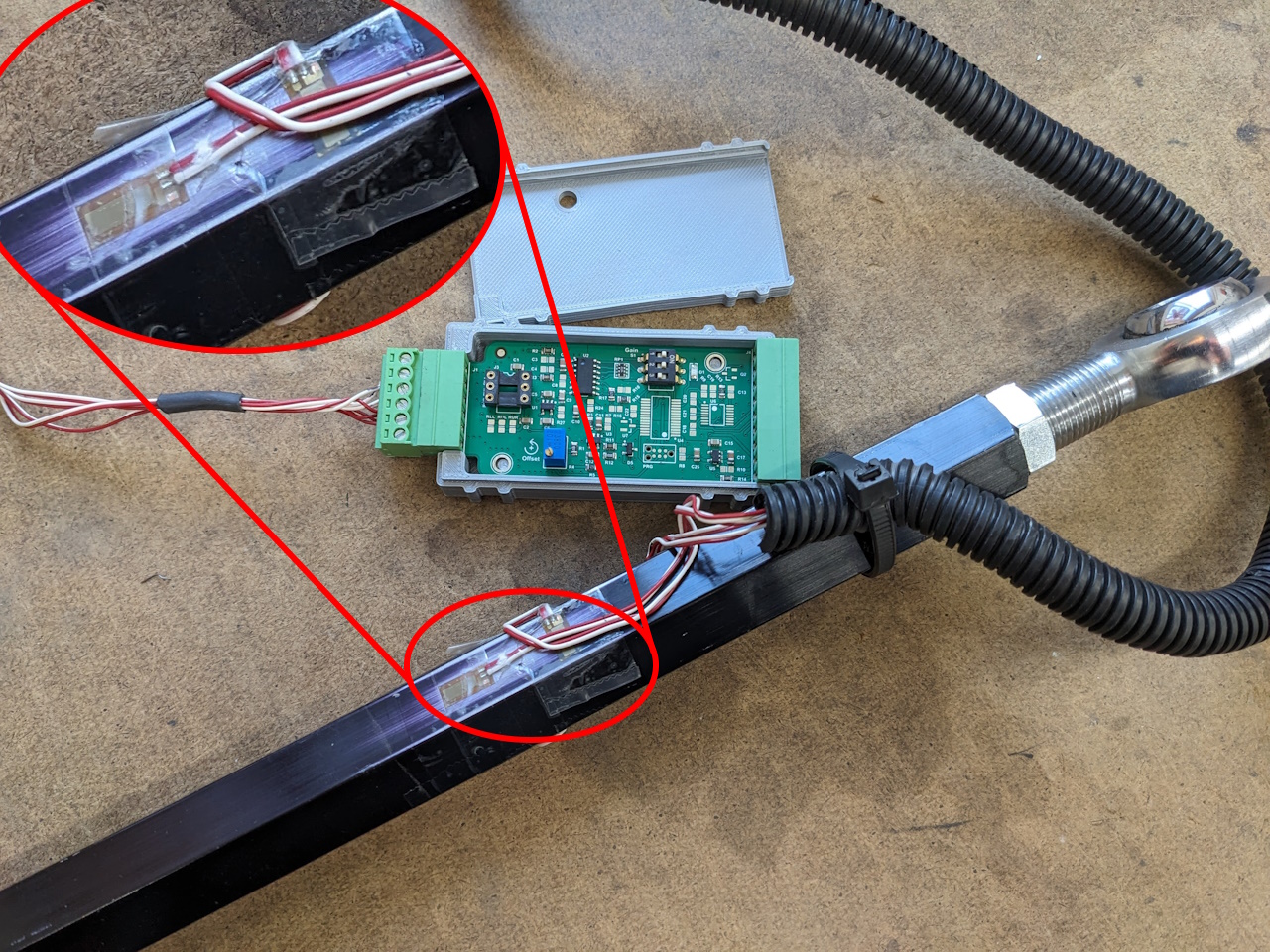
I installed four gauges on a tie rod tube in a "full bridge" configuration. A full bridge consists of two gauges lengthwise and two gauges crosswise. This allows temperature effects to be automatically canceled out, and increases the output vs a half bridge (one lengthwise and one crosswise). The basic wheatstone bridge circuit is shown below, with R1 and R3 being the lengthwise strain gauges and R2 and R4 being the crosswise gauges. The surface was scuffed with sand paper and the gauges glued in place with super glue. Scotch tape was used as a backer while gluing to prevent me gluing my fingers on as well. After gluing the gauges in place the whole thing was wrapped in electrical tape to protect the gauges and wires.
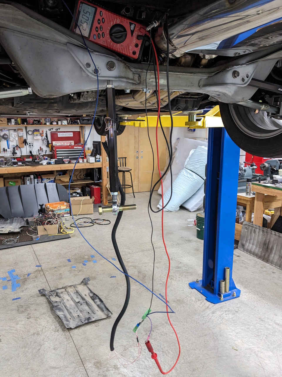
Using information from a variety of sources on the internet plus the calibration data for the strain gauges and amplifiers I built an excel sheet to calculate the expected voltage output for a given load on the tie rod. The handy thing about this whole setup with the tie rod is I could disconnect the outer end of the tie rod and with the car the the lift, apply a known weight (my body weight) to the tie rod to check the calibration. It was extremely satisfying (and I'll admit a little surprising) to see the voltage output match exactly to the expected value, to within .001v. Ultimately all of the calibration calculations were more or less just an exercise to prove that it works, as with this setup I could have simply calibrated it directly with a known weight and skipped all the math. It may prove useful in the future however.
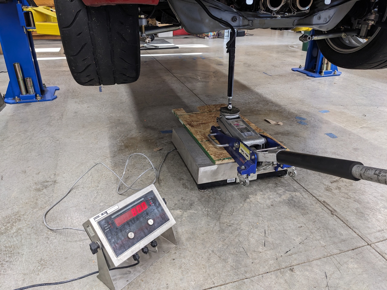
After initial verification with a multi meter and raw voltage readings I hooked the output of the amplifier up to my Race Capture Pro data logger and configured it with an equation to convert the voltage value to a force value before logging. The level of sensitivity of this setup is pretty amazing. I can grab the wheel with my hands and push / pull on it and see the force values in the tie rod change, down to a few pounds of force. Much later I rechecked the calibration to further verify the data I had gathered in testing. The verification was done with a heavy duty scale and a jack, as shown below. Strain gauge readings matched the scale within about 1% up to 400lb, which is plenty of accuracy for my purposes.
The Results
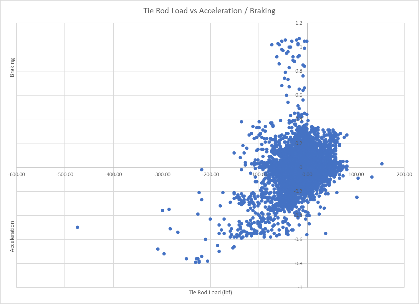
Initial street testing yielded the following results. Negative force values are compression in the tie rod, positive values are tension. Not too surprising, there is very little load on the rear tie rod due to braking. Under acceleration the load on the tie rod is compressive, which seems backwards compared to what I expected given the geometry of the tie rod and the suspension (scrub radius, etc). However I checked and double checked that I had everything configured right and it all matched. Remember that it is quite easy to verify the load by pushing on the wheel by hand and watching the readings.
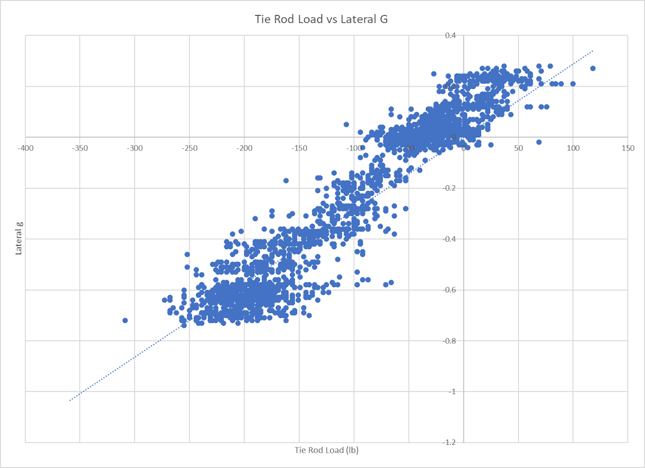
Lateral acceleration around a long cloverleaf on ramp produced a nice concise correlation between lateral g and tie rod load, which extrapolates out to about 350lb/g.
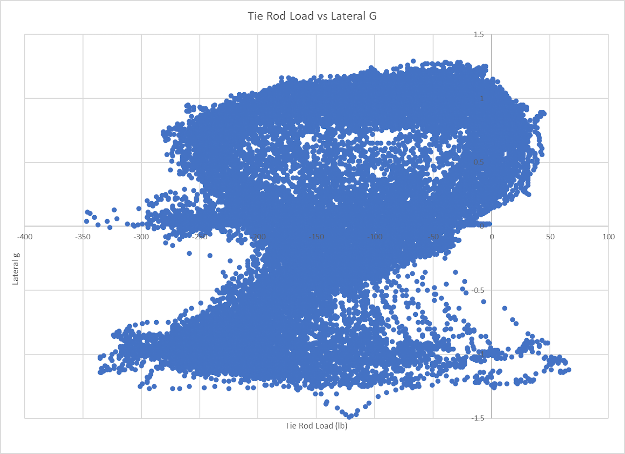
I also collected data at an autocross event. Below is all of the tie rod load data from 10 autocross runs, plotted against lateral g. Interestingly, despite seeing lateral acceleration in the 1.2+g range, peak tie rod load barely exceeded 330lb, less than my previous street testing predicted. I can think of a couple possible reasons for this, one being that you are almost never just turning or just accelerating in autocross, you are almost always doing both at the same time. It is possible that the combined loading actually cancels out some of the load on the tie rod. It is also possible that as lateral load increases the tire deforms enough to significantly change the scrub radius, reducing the rate at which tie rod load increases relative to lateral load.
For those who may be looking to apply these results to their own project, keep in mind that suspension geometry will have a large effect on the total load seen on a part like a tie rod. The MR2 rear tie rod is offset quite a large distance from the center line of the wheel, giving the tie rod a large mechanical advantage to react any forces generated by the tire. So while these numbers may give you an order of magnitude value for tie rod force, a lot of variation is certainly possible. Best to take your own measurements!

