Have you found the electronic throttle on your 2GR swapped MR2 to be a little too sensitive? It turns out, there is a reason for that, and also a $15 solution!
If you log (using Torque Pro or your favorite OBDII logger) pedal position vs throttle position and graph them against each other you will generate a graph like this:
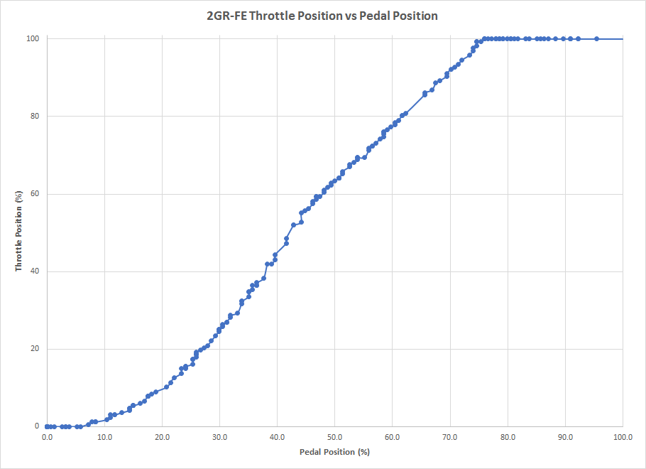
I used PIDs "Accelerator PedalPosition D" and "Throttle Position(Manifold)", and then normalized them so that they read from 0-100% (the actual ranges you get from Torque will be different, but the shape of the curve is the same). Notice that the throttle is fully open when the pedal is at about 75%. This means that the top 1/4 of the pedal travel doesn't do anything, and all of the throttle control is compressed into 3/4 of the pedal travel. The question is, how do we fix this?
The throttle control circuit is actually pretty simple. Three wires: one ground, one constant voltage supply, and one voltage signal back to the ECU (x2 because there are two separate / redundant circuits). I had previously tapped into the signal wire to log pedal position with my Race Capture Pro data logger, so I had a decent idea of what this voltage signal looked like. Since the pedal signal to the ECU is "too high" (causing it to reach 100% throttle at 75% pedal), all we need to do is drop the voltage a little. My theory was that a voltage divider between the signal wire and the ground wire could do just that.
This needs to be adjustable so that the exact correction can be dialed in. Since there are two parallel circuits for the throttle, and since the relationship between those two circuits must be maintained in order for the ECU to stay happy, a dual channel potentiometer is the solution (I used a 10k Ω linear pot). For my first test I wired it up using some scraps of wires with ECU pins on the end (left over from all the wiring I removed when wiring the swap... I never throw anything away). That looked like this:
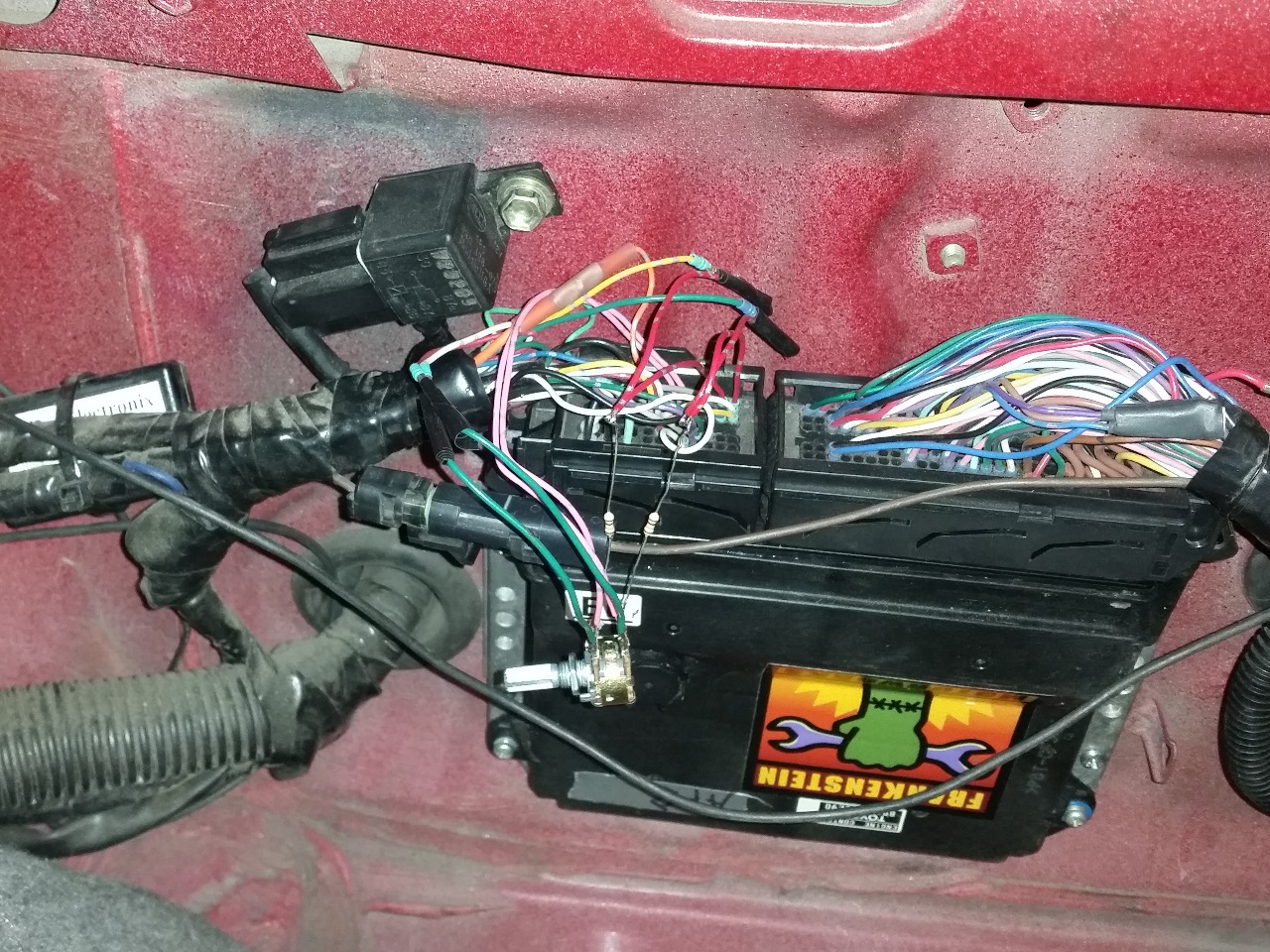
Initially I just used the potentiometer, and while it worked, the adjustment was very sensitive making it hard to dial in exactly the right value. I then added the two 10k Ω resistors that you can see in the photo, which made the adjustment significantly easier. The wattage rating on this resistor isn't critical, but higher wattage resistors will have heavier wires and should be more durable / less likely to fail due to vibration. Mine are standard 1/4w resistors, but I am thinking of swapping them out for larger versions for this reason.
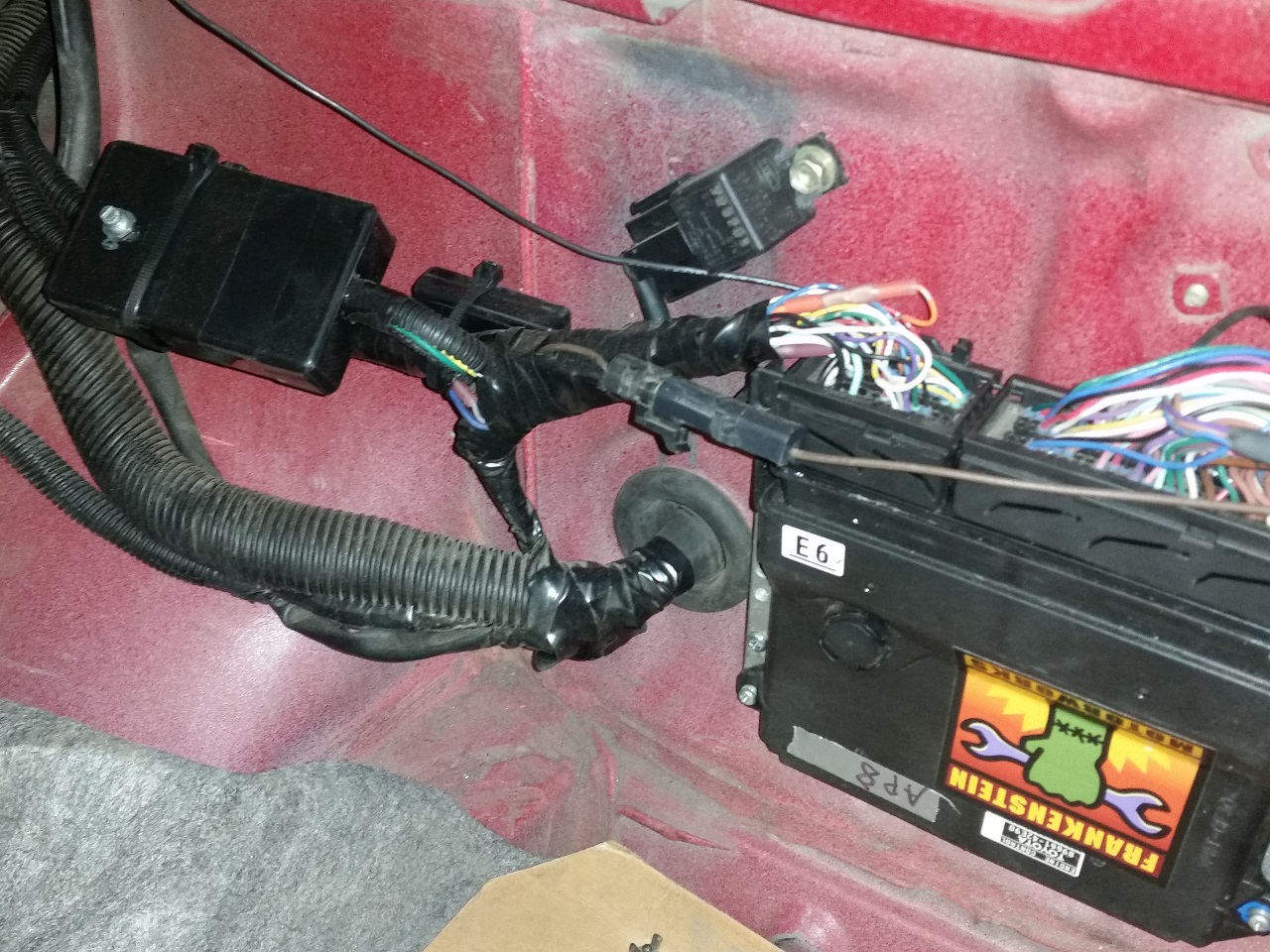
With testing complete I moved the potentiometer and resistors into a small project box and spliced them into the wiring to the ECU:
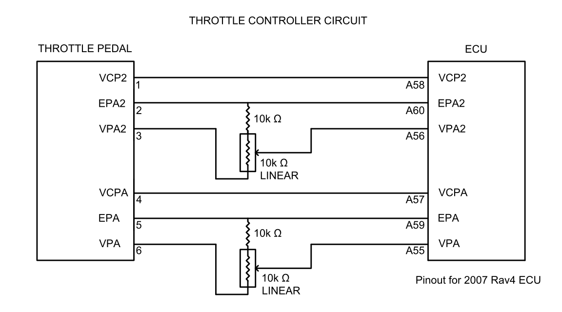
The circuit diagram with this added looks like this. Note that the ECU pinout is only valid for the pre 2010 Rav4 ECU. Please consult the wiring diagram for your ECU if you wish to build one of these yourself. I *believe* the throttle pinout is the same for all compatible throttle pedals.
Tuning the controller simply requires holding the throttle fully open and slowly adjusting the potentiometer while monitoring the values of the pedal position and throttle position PIDs. The pedal position PID should decrease as you make the adjustment, while the throttle position value should remain constant. When the throttle position value drops from it's normal max value, turn back just slightly to ensure that you can still achieve full throttle, and you are done. Note, I have found that if you go to far you will trigger a limp mode where the throttle won't open more than about 20%.
Graphed like before, the result looks like this:
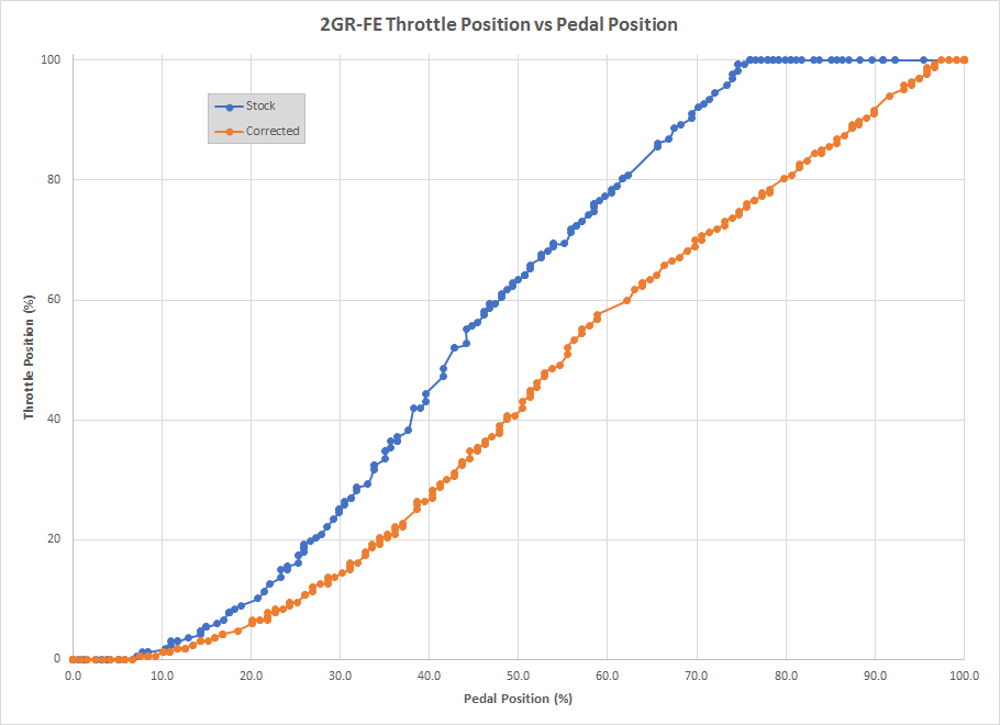
The result is a very noticeable decrease in throttle sensitivity, and a big improvement in ease of throttle modulation.
Update Sept-16-2019
It may be due to using a cheap potentiometer, but I messed with the adjustment on my controller recently and after that I had a throttle code in the ECU that I could not get rid of. I ended up rebuilding the controller using fixed resistors. This does take a little trial and error to get right, but I think will provide a more reliable solution. I started by looking at the amount of correction required (a little less than 25%), and calculating a voltage divider to provide that amount of drop (a 3.3k and a 12k resistor, 3.3k/(12k+3.3k) = .22). This produced some odd results, as you can see in the chart below. I reduced the small resistor to 3k (3/(12+3) = .20), which was much closer, but still just a tiny bit too much as it was clipping the top couple percent of the throttle opening. So I reduced one more time to 2.7k (18% reduction), which turned out to be just about perfect for my combination of (Denso) throttle pedal and Frankenstein Motorworks 2-plug ECU. A different combination of resistors MAY be required for other setups!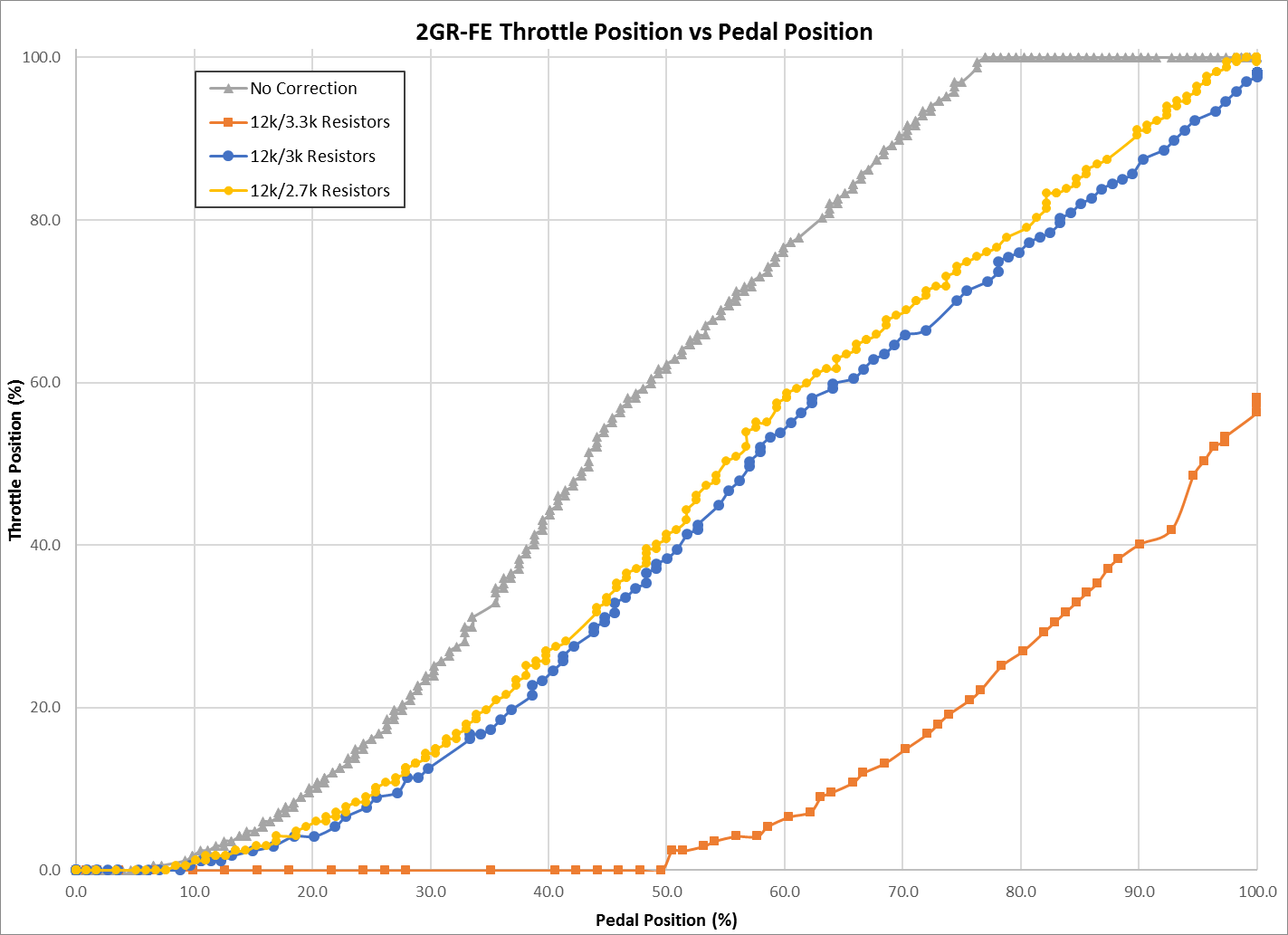
Interestingly, there seems to be a point somewhere around 20% correction past which a small amount of additional correction triggers some odd mode in the ECU where it dramatically limits the throttle. You definitely want to test to confirm that this isn't happening before finishing your controller.
To finish this new version, I wrapped the resistors in heavy duty heat shrink tubing, and slipped a piece of a plastic zip tie inside the tube as well to stiffen the whole assembly and hopefully prevent the relatively delicate legs on the resistors from being exposed to any stress. The circuit diagram for this version can be found below.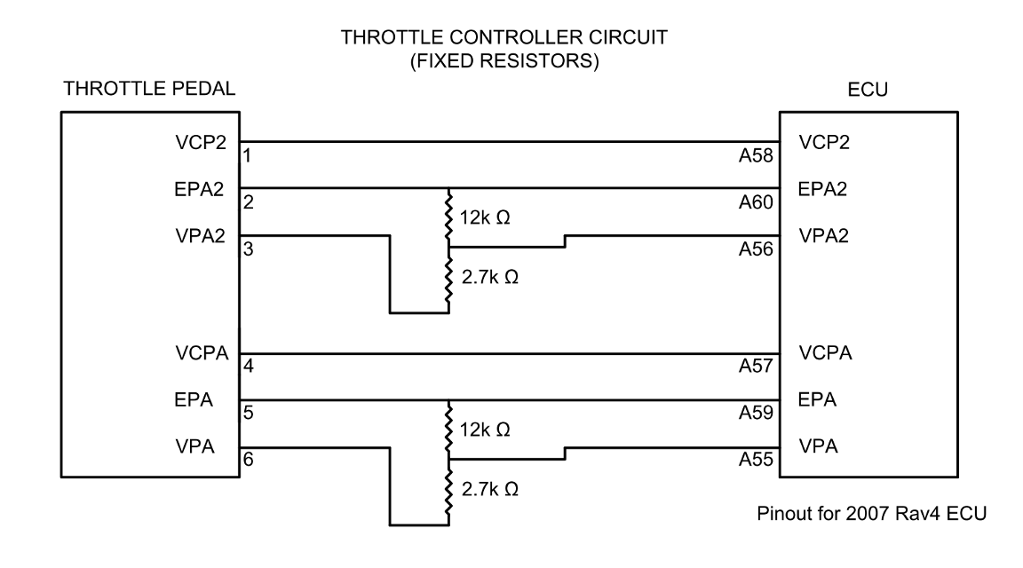
Disclaimer! If you attempt this yourself, please make sure you know what you are doing and are comfortable with reading wiring diagrams, soldering, and basic circuit design. Remember that you are messing with the link between the throttle pedal and the ECU. The most likely result if something goes wrong is an unresponsive throttle (which could leave you stranded), but I won't rule out the possibility of some sort of "unintended acceleration" situation if something were to short out in the controller. I also do not know if this will have the desired effect on a stock setup with the automatic transmission, or if it would even be applicable in that situation.