There's always room for improvement. My SLA rear suspension conversion worked well in the limited testing I have done, but there were just a few things design wise that I wasn't completely happy with. So on to V2.0.
Design
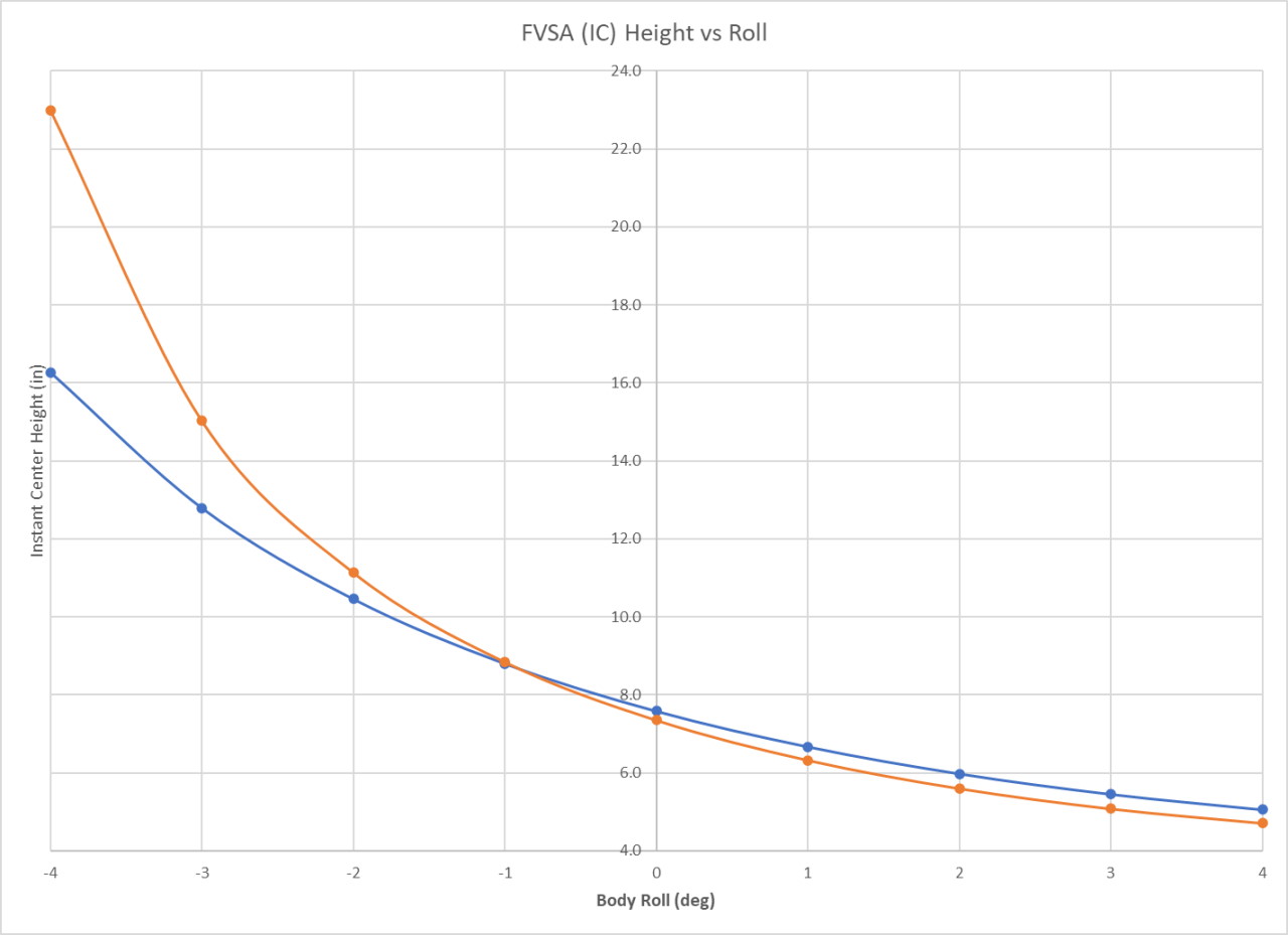
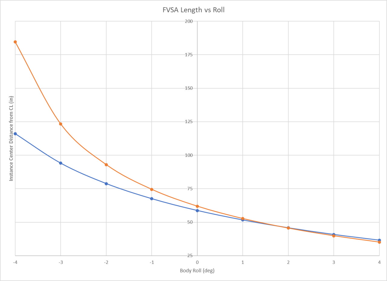
The main thing I didn't like about the original design was the length of the upper arms. They were just a little on the short side. And while the camber curve and toe curve was both good, some of the "secondary" parameters didn't look a nice. Mostly I'm talking about the movement of the instant centers, which where moving quite a lot as the suspension moved. Some people will say that the movement of roll centers (and instant centers) doesn't really matter much, but I have always felt that when any of these sort of parameters changes rapidly it's not a good thing. It certainly seemed to me that reducing roll center movement on the strut suspension improved the overall "feel" of the suspension. Here's the before (orange) and after (blue) graphs of the instance center positions vs body roll. Note that this only shows the left side of the car, and positive body roll is a turn to right while negative body roll is a turn to the left. Ultimately this means that I have mostly improved the unimportant side (outside / unloaded side) of the suspension, but hey, every little bit helps (I hope!).
 |
 |
The other thing I didn't really like was the upper ball joint which put all of the load into a single bolt threaded into the aluminum adapter. It was a big bolt, but even so, it just didn't feel... motorsports grade. I also have been wanting to redesign the lower control arm to put all of the pivots in the same plane, allowing the arm to be built lighter without losing effective strength. This was a perfect opportunity to accomplish that as well.
Lower Control Arm
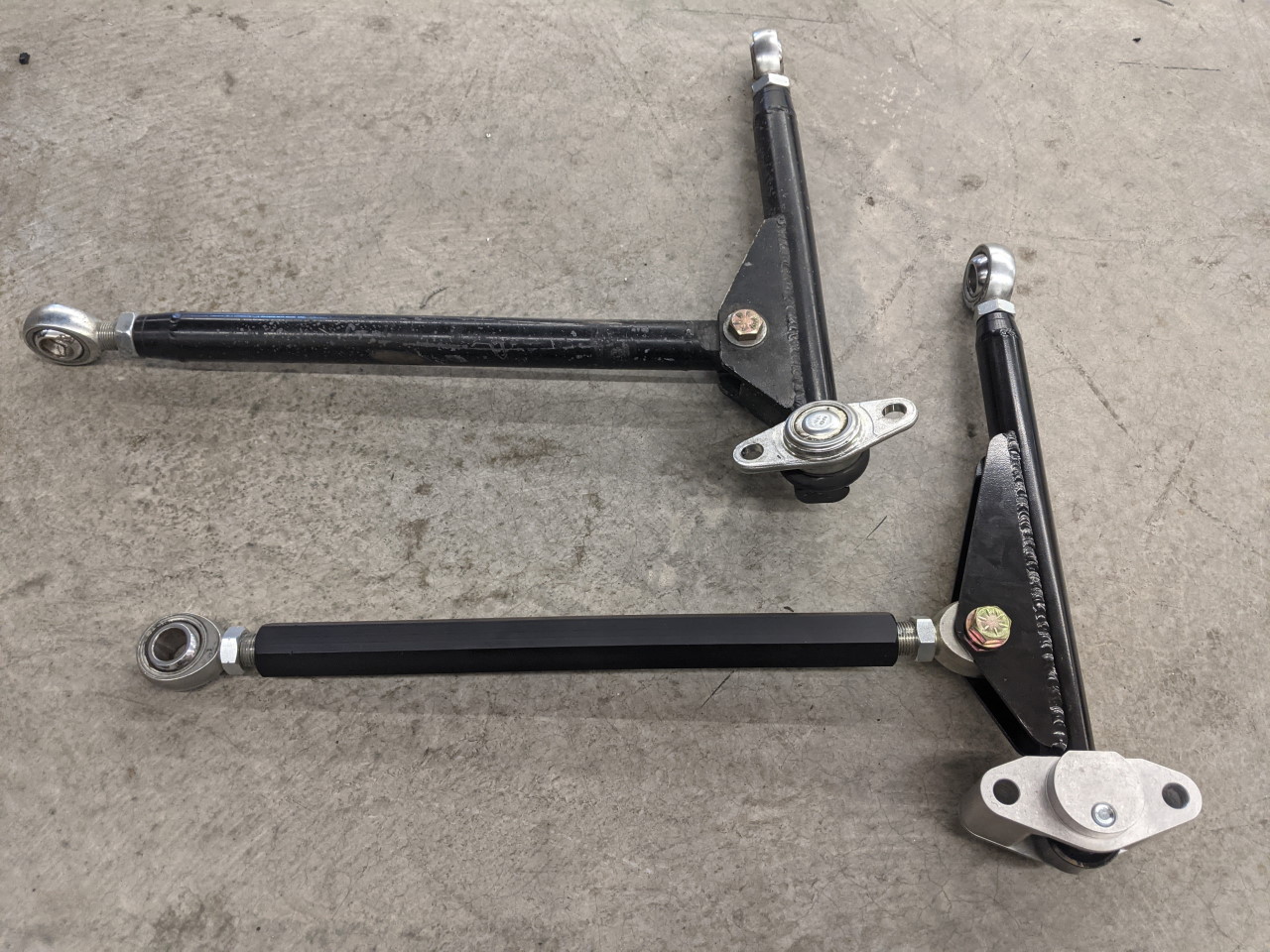
The redesign of the lower arm and ball joint actually ended up being the key to the whole project. I converted the ball joint to double shear with a machined aluminum adapter and a 4130 chromoly plate. Converting it to double shear makes everything much stronger, and allowed me to comfortably downsize the pivot bolt. This allowed me to downsize the spherical bearing as well, giving room to move the pivot point outboard by 1/2" without running into the brake rotor. Here's a picture of an early prototype with 3D printed parts and the control arm just tack welded together.
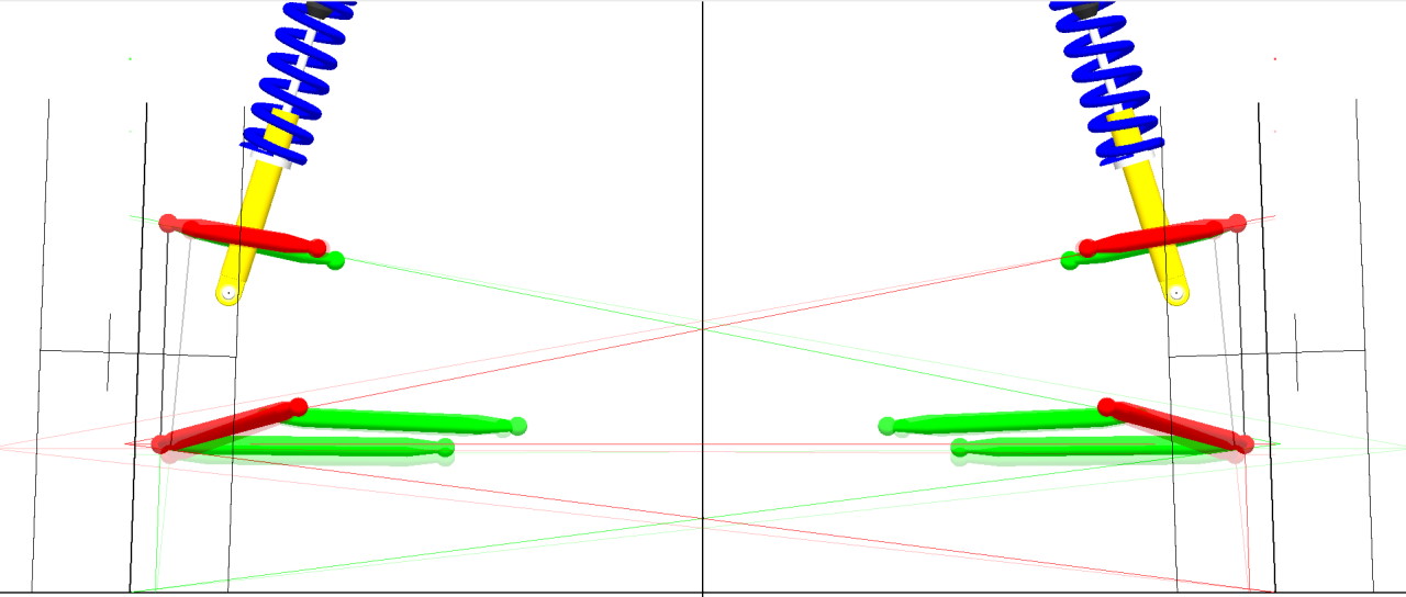
"But Alex, you said you wanted to lengthen the upper arm, why are you lengthening the lower arm??". Good question. One of the reasons the upper arms ended up the length they did the first time around was that I didn't want an excessively large scrub radius. Scrub radius may not be AS important on the rear as it is on the front (where it impacts steering feel), but it does effect the amount of force that goes into the tie rod, so I didn't want it to be TOO large. Lengthening the lower arm by 0.5" allowed me to lengthen the upper arm by 1.2" without significantly changing the scrub radius. The overlay below (new design is solid, old design is transparent) shows this more clearly than words can describe it. Notice how the kingpin axis (the line between the upper and lower ball joints) intersects the ground at the same point despite the longer upper arms.
I seriously considered doing something custom with the brakes at this point (thinner hat, modified bracket, etc) to push the brake rotor out and make room to lengthen both upper and lower arms by another 1/2" or so. This would have had the additional effect of further decreasing the scrub radius, but it would have required either modification of the caliper as well (or switching to a different caliper), and I just decided that it wasn't worth taking it to quite that level. Another option I considered was purchasing new higher offset wheels and lengthening the arms that way (pushing the entire hub and knuckle further into the wheels). But again, further than I wanted to go. I have multiple sets of wheels already, and high offset wide wheels are hard to find (they probably would have to be custom in fact). This was the best middle ground compromise.
As I mentioned previously I was able to build the lower arms lighter due to the redesign. The stock ball joint where the ball joint pivot is above the plane of the control arm creates significant bending loads in the arm that are eliminated when you move the ball joint pivot down in plane with the arm. Thinner and smaller diameter tube (1.125 x .083 chromoly), thinner tabs (.125 chromoly vs .188 mild steel), and an aluminum strut rod instead of steel. All in all the lower control arms saved 3.2lb each compared to my old fabricated arms, which were already about 1.2lb each lighter than stock control arms.
One of the other advantages to the double shear ball joint is I was able to do this conversion to an in-plane ball joint while also raising the ball joint closer to the knuckle. With the double a-arm suspension, less roll center adjuster is required to achieve my target roll center height. If you remember my original design had required me to space the cross member down in order to get the geometry I wanted. This will allow me to eliminate those spacers, although I may still use a smaller spacer here to fine tune the roll center height.
Upper Control Arm
For the new upper arm, I again converted to double shear, and turned the pivot axis sideways instead of vertical. The one drawback to this is I lose the ability to adjust the position of the upper ball joint without making a new (expensive) machined part. But it was necessary as I was running out of room between the inside of the wheel and the ball joint. This just barely clears my 17" RPF1s, and a vertical ball joint with a stud and nut on top just wasn't going to fit. Plus this just has a nice OEM+ look to it, and I think will be stronger. It's finished off with a chromoly strap to "tie down" the outside edge, taking some of the bending load from the aluminum part and putting it into tension in the strap.
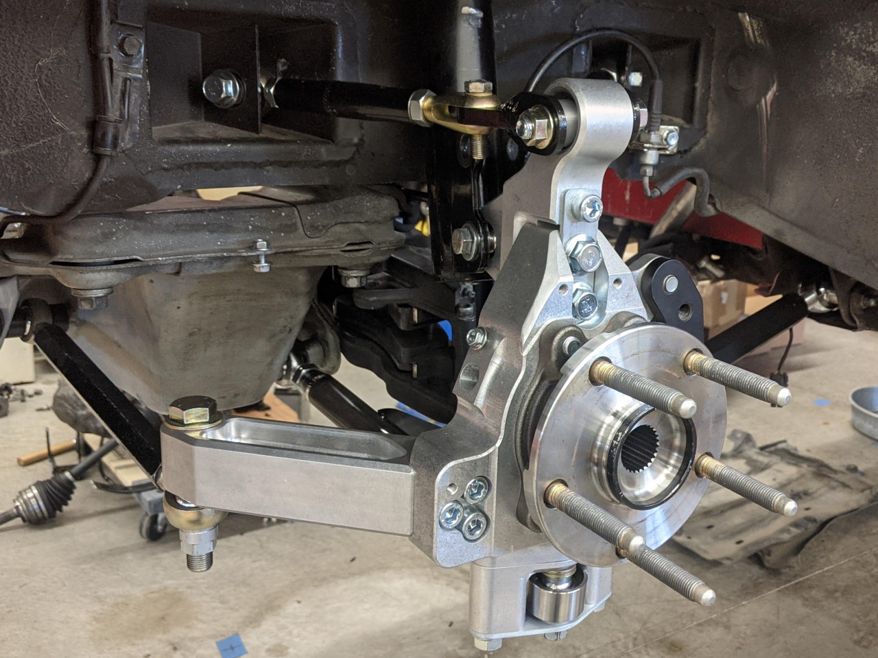
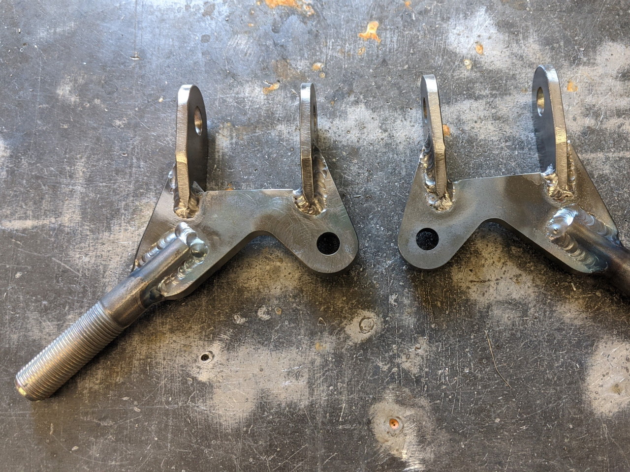
The new upper control arm consists of a welded assembly similar to the old one, but with a double shear clevis instead of the old versions spherical bearing. If you remember v1 had a pair of clevis fittings that attached to the bearing plate, one of which was welded in place to prevent rotation. I was never 100% happy with that design, even though the analysis said it should be totally fine. This with the more solidly welded threaded stud should be stronger AND is more professional looking (in my opinion). The second clevis fitting is still necessary to allow the angle of the arm to adjust slightly when setting camber, as well as to allow the upper arm to be installed as it won't go in in one piece due to the angles of the boxes in the frame. Weight wise, the upper arm basically broke even. Some pieces are a little heavier, some a little lighter, it ended up virtually identical in weight to the old version.
Bump Steer Fix
One side effect of the revised ball joint (and elimination of the cross member spacers) was that the optimal position of the rear tie rod at the knuckle was going to be inside the end of the toe arm. I had expected this, based on the suspension model, and when I checked bump steer after the initial install of the new parts, it was exactly as I expected. About .1" of toe change per inch of travel. There were two ways I could fix this. One would be to tilt the entire knuckle forward (essentially adding negative caster, although for a non-steered wheel it doesn't function as caster). This would cause the toe arm to angle up, raising the tie rod pivot. But this also complicated the geometry in other ways, and just didn't seem like the ideal solution. But I had already added a new tie rod point in the cross member, and it is relatively easy to add another. With the longer upper and lower arms a longer tie rod is also appropriate, so I moved the tie rod point again, this time down and slightly inboard from the v1 position (if the outer end of the tie rod needs to go up, you can accomplish the same geometry change by moving the inner end down).
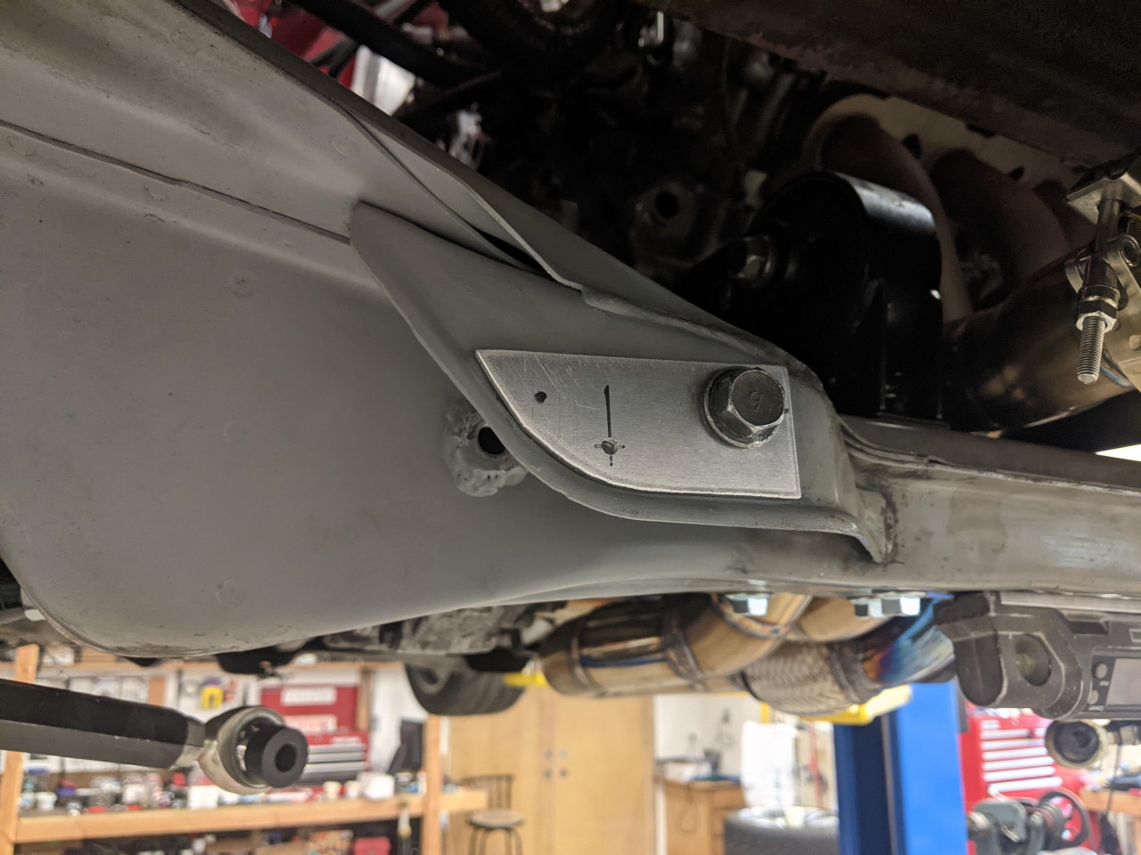
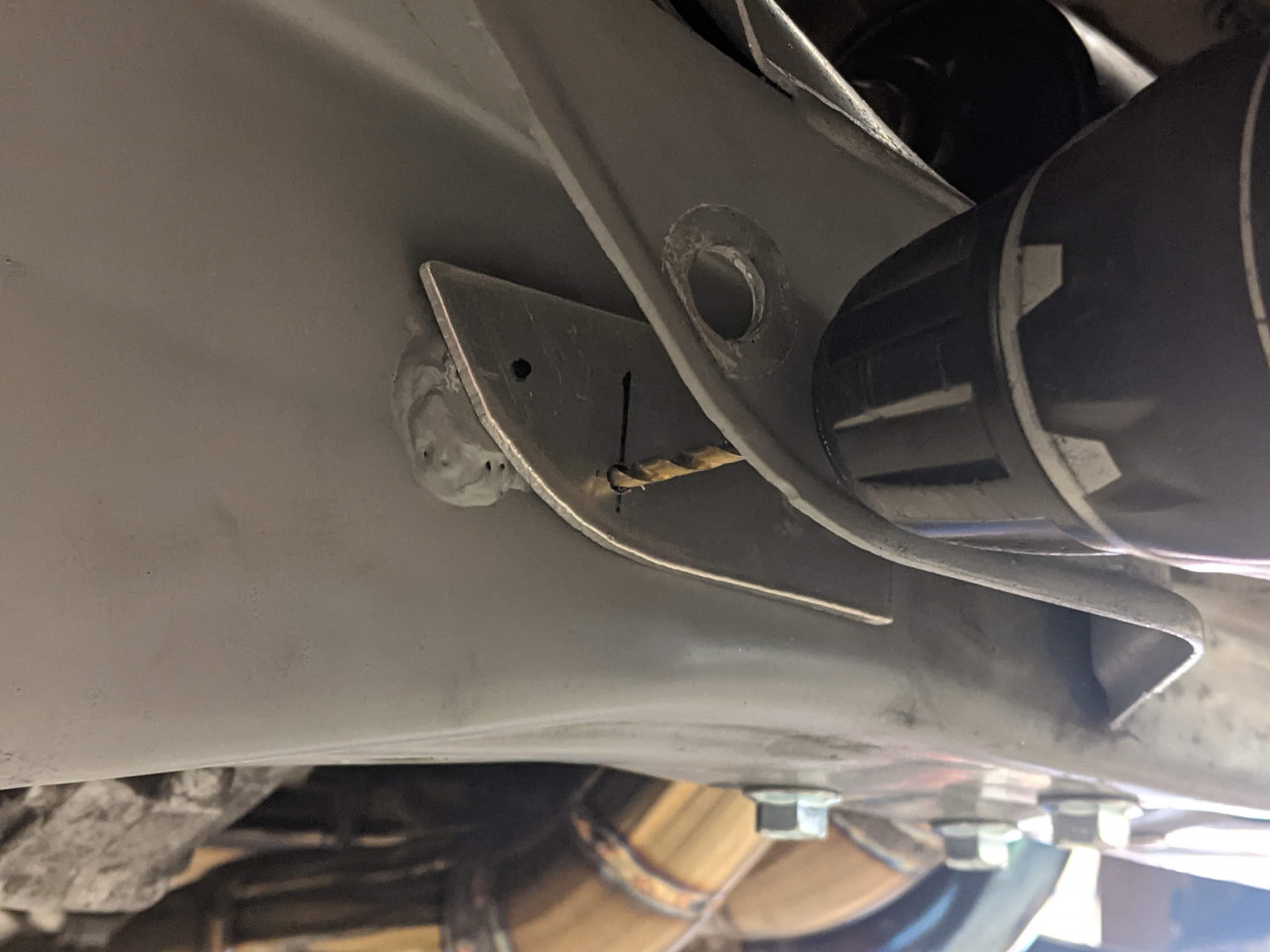
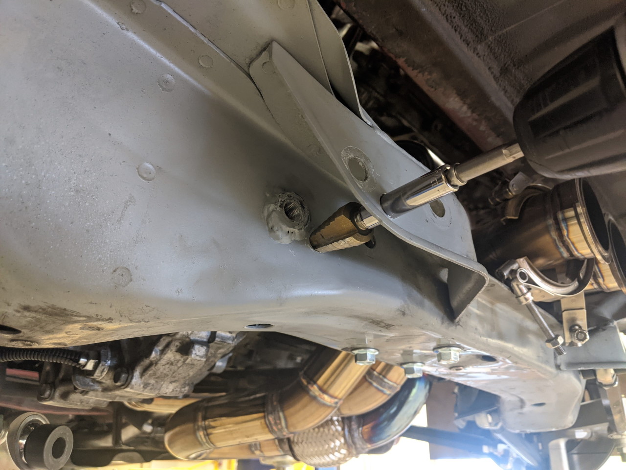
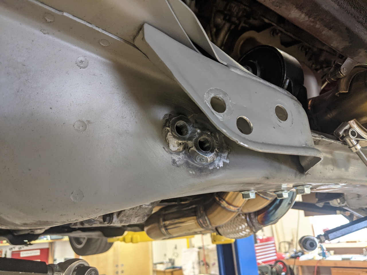
As before, I made a template to allow me to easily get the holes in the same place on each side. Use the template to drill a 1/8" pilot hole, then moved the template to the inside and drilled a second 1/8" pilot hole in line with the first.
 |
 |
The holes are then both drilled out to 1/2", and that's when things get tricky... In order to insert the weld in nut (modified M12 flange nut), I need to enlarge the inner hole to 5/8", without changing the outer hole... A step drill driven with a socket does the trick. I had to slightly shorten the shank on the step drill to get it into place, but it was the easiest and most precise way to accomplish the goal. Weld in the new nut, and done. I may have an excessive number of tie rod attach points now!
 |
 |
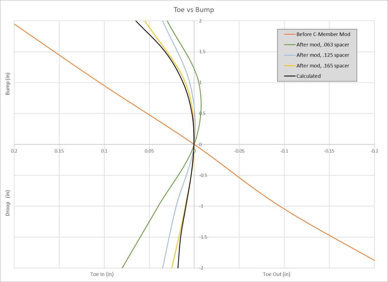
With the revised cross member, I checked bump steer again. I ended up adding about .1" of spacer above the rod end at the knuckle, which gave me a measured toe curve nearly identical to what my model had predicted. It only took about .05" more spacer than the model had predicted, which is a very nice validation of the accuracy of both the model, and the location of all of the new pivot points. Here's a graph of the toe curve before the latest crossmember mod, plus after bump steer adjustment.
It turned out, when Apex Attack put this to the test on the track, that this modification to the toe curve had resulted in too little toe in, resulting in some instability especially under braking. The solution instead was to go back to the stock toe arm position on the cross member and modify the toe arm on the knuckle to raise the pivot point to match, as shown below.
If (WHEN!) this makes it to a production / for sale kit, this is what I expect it to look like!