There's a lot of things to like about the MR2, but the McPherson strut rear suspension really isn't one of them. But that's so thoroughly baked into the design of the car that we couldn't possible change it, right?
Right?!?
Design
Improving the suspension on the MR2 has been both a hobby as well a business for me for more than 10 years now. I had reached a point where I didn't see much else that could be done to optimize the strut suspension, and the rear strut in particular still isn't great even with all the improvements I have been able to make to it. I had also constrained myself for years to working within the rules of the SCCA Street Modified autocross class (which requires stock suspension points on the chassis). But with the advent of the new Extreme Street classes last year, a lot more was suddenly open to me.
The main goal is to significantly improve the camber curve. That will allow less static camber to be run to achieve the same camber under cornering load, improving grip under all conditions. Reducing roll center movement is another benefit. The design started in parallel with (and as an add-on to) my aluminum rear knuckle design. I spent dozens, perhaps hundreds, of hours exploring different ways to achieve what I wanted. The design actually started out as a multi-link suspension similar to that used on the Porsche 996 and 997, but I eventually realized that performance wise there wasn't much if any benefit to that, and it complicated some aspects of the design. It also would have simplified some other aspects. Advantages and disadvantages to both. You can read a little more about the design and some of the iterations I went through in this thread on the MR2oc Forum.
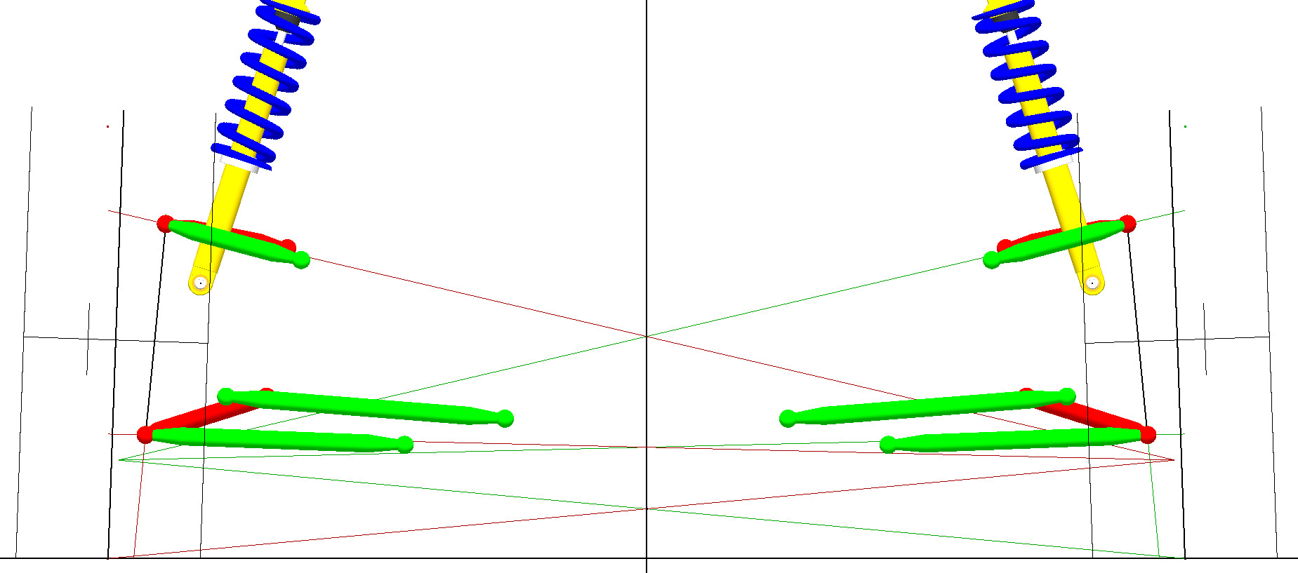
In the end, I settled on an SLA (Short Long Arm) double wishbone design, the rear view in Susprog looks like this:
I also created 3D CAD models of most of the rear suspension and a rough representation of the side of the chassis so I could design the attachment points.
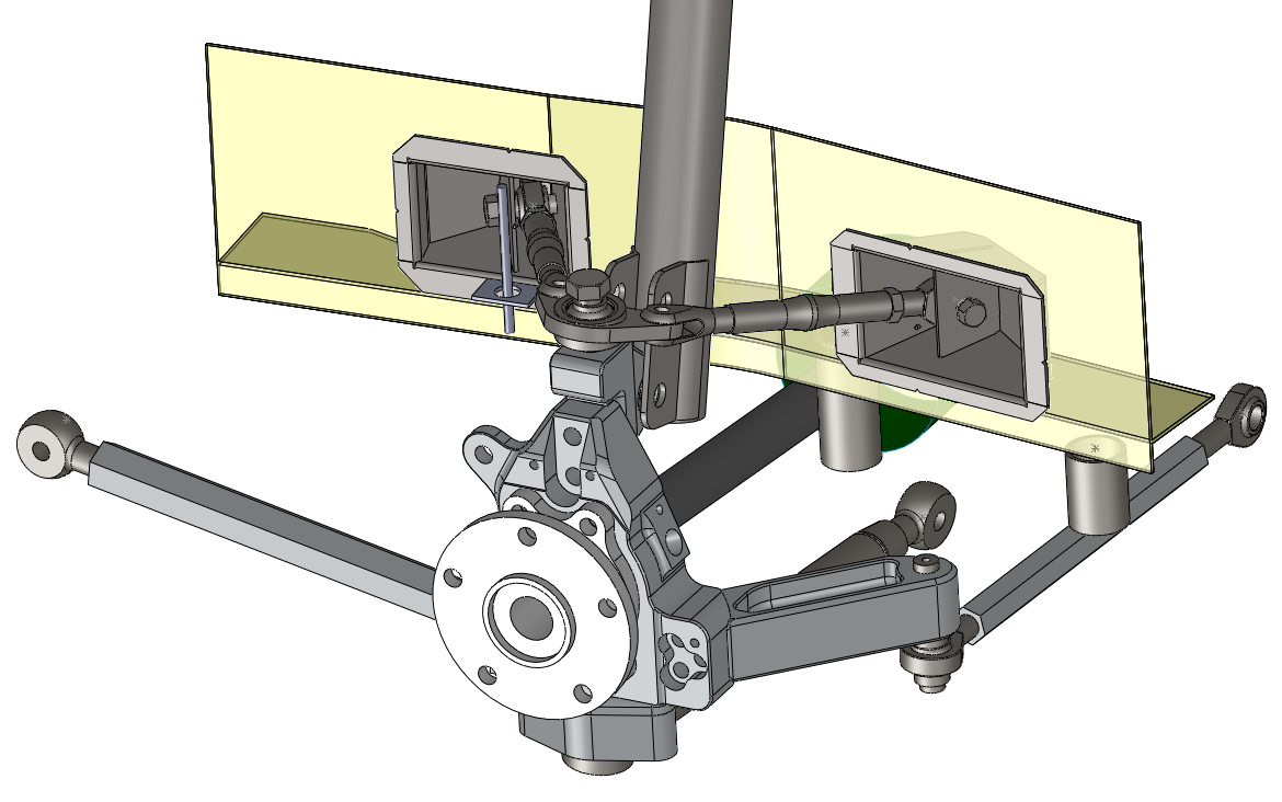
The upper arm mounting points are recessed into the side of the chassis to increase the upper arm length, and angled so that a socket wrench with an extension can still be used to tighten the bolts. Recessing the pivots like this gained me about 2in of length on the arms compared to surface mounting them. The arms ended up about 8in long, so that 2in is quite significant.
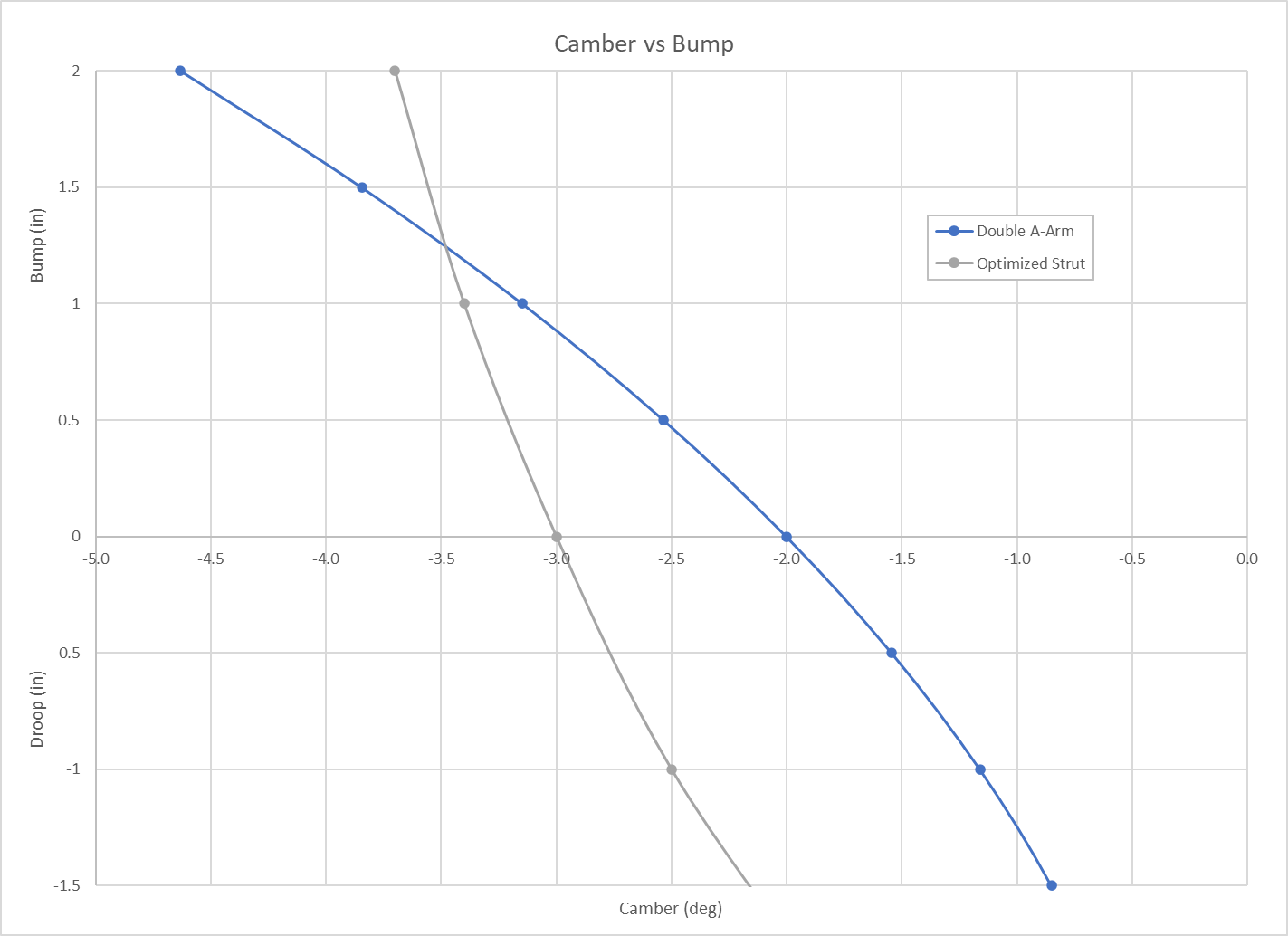
What this gives me are camber curves that look like this:
 |
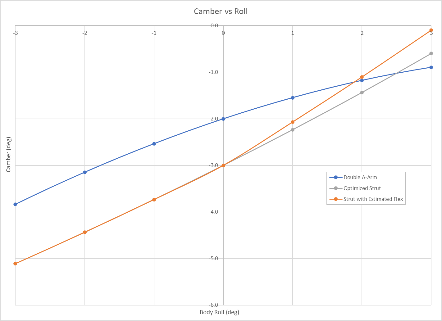 |
One disadvantage to the strut suspension that doesn't get talked about much is how much the strut itself flexes. The orange curve in the camber vs roll graph above represents an estimate of the camber curve once strut flex is taken into account (based on the stress analysis that was done on my new knuckle design). The gray curves are the strut camber curve with all of the optimizations I have done. The stock camber curve is quite a bit worse than this, especially on a lowered car without geometry correction. As you can see I should be able to run about 1° less static camber (-2° instead of -3°) and still have equal camber at 2° body roll and significantly better camber at 3° body roll.
Using the stock 91 (short tie rod) cross member with the double A-arm suspension will produce a toe curve very similar to the stock 93+ (long tie rod) toe curve. I may in the future add an additional mounting point on the cross member to shorten the rear tie rod to reduce the amount of toe change, but for now I will give this a try.
Fabrication
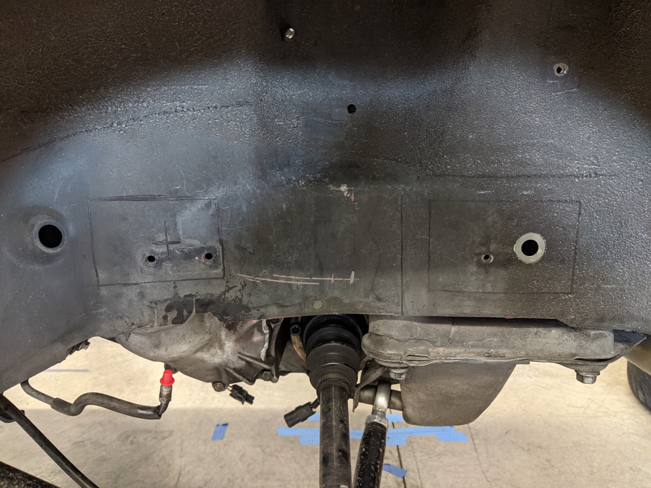
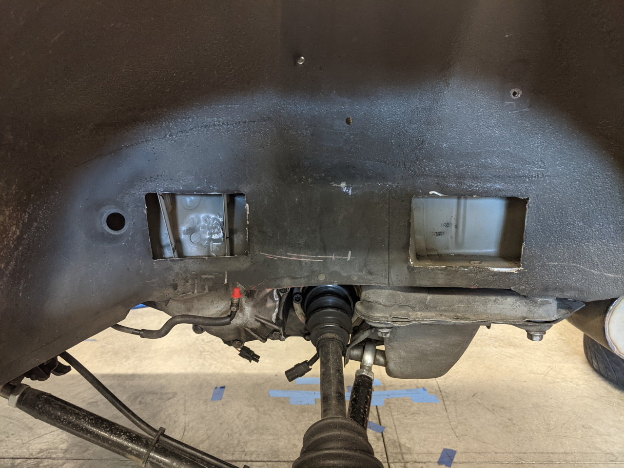
With the design done, or at least as done as it could be without a real world prototype, it's time to cut some metal. Using my model as a guide I laid out the locations for the holes using the forward cross member bolt as a reference point. As you can see I am cutting away the brake line mounting point and the ABS wire mounting point. Will deal with those later.
I will admit I stalled a bit here, second guessing if I REALLY wanted to cut those big holes in the side of the frame.
 |
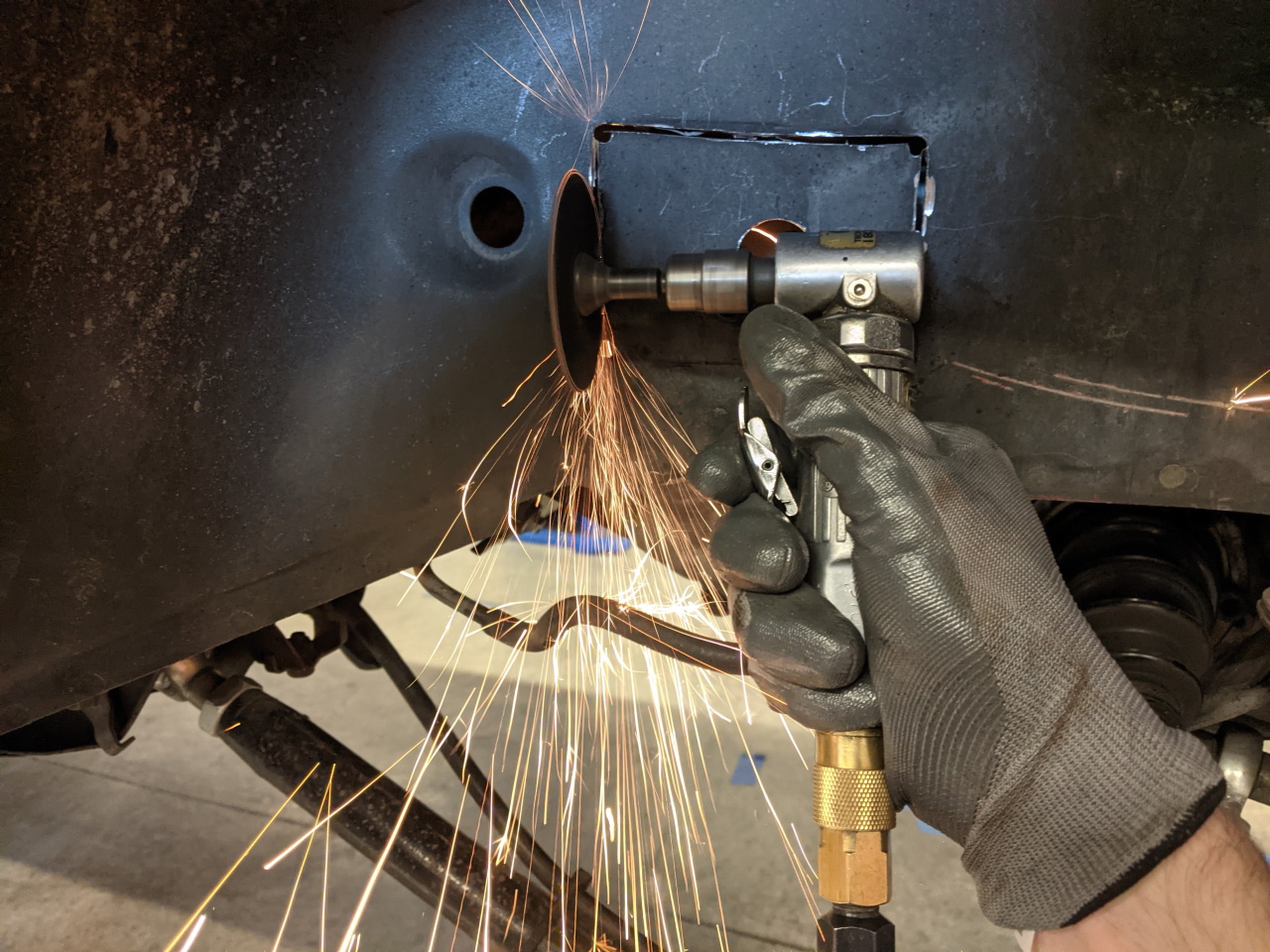 |
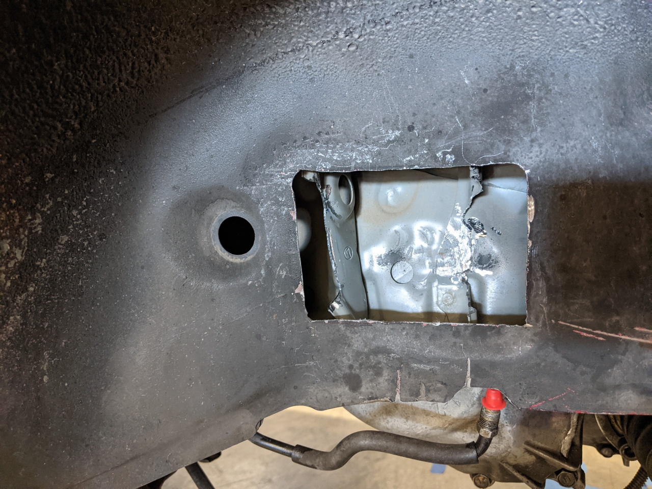
Holes cut for the LH side boxes! There are two reinforcement ribs behind the forward hole (the motor mount is right above this area) that I will have to notch to clear my a-arm box. Also the frame rail is quite thin at this LH forward location, due to a recess on the far side to clear the transmission. I notched the ribs just enough to clear, and also worked on the far wall just a little with a hammer to make room for the boxes. Just trying to maximize the length of those upper arms.
 |
 |
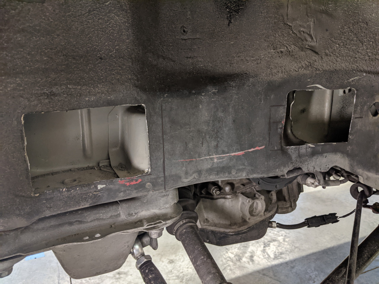
Repeat the process on the RH side. Only one reinforcement needed to be modified here (there is another, but it is further rearward).
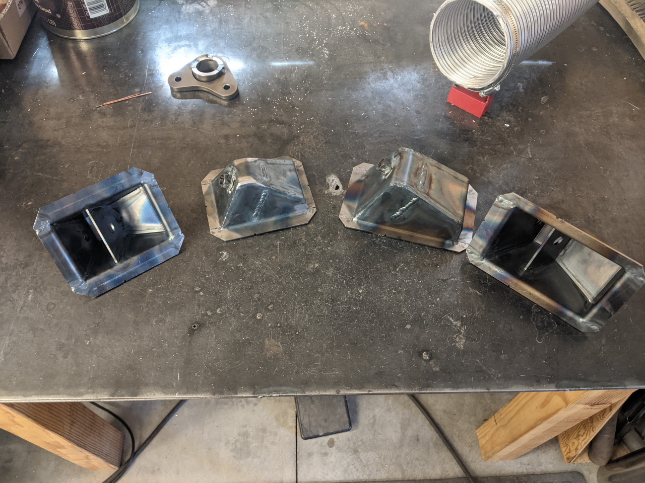
And finally, test fit my box design with some 3D printed prototypes. These will be laser cut and CNC bent by the local sheet metal shop that does most of my sheet metal work.
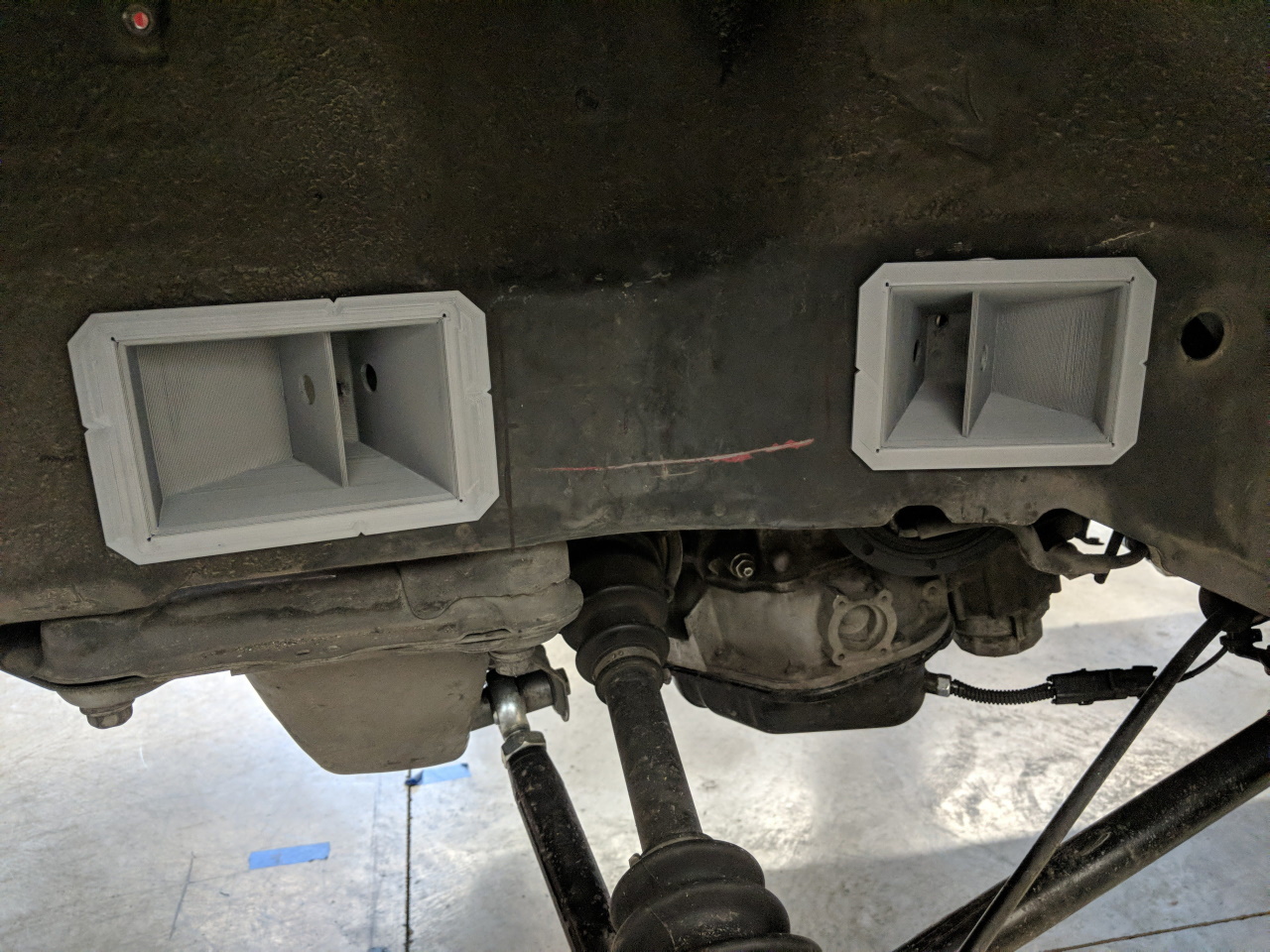
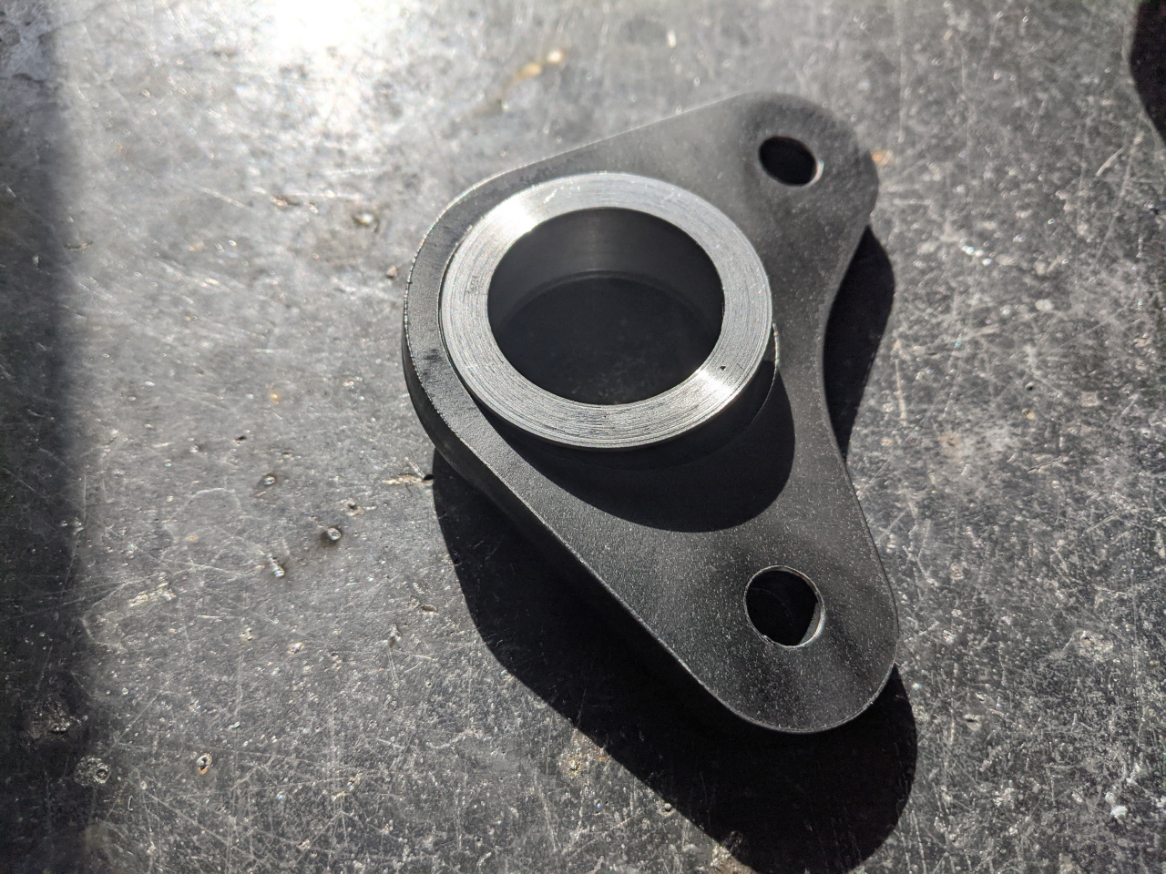
Speaking of laser cutting, I had these custom plates laser cut for the A-arm bearing cups. The hole in the center is oblong to allow the cup to be mounted at an angle to allow the require amount of travel in both directions. The boxes are each composed of four pieces, welded together as you see here.
 |
 |
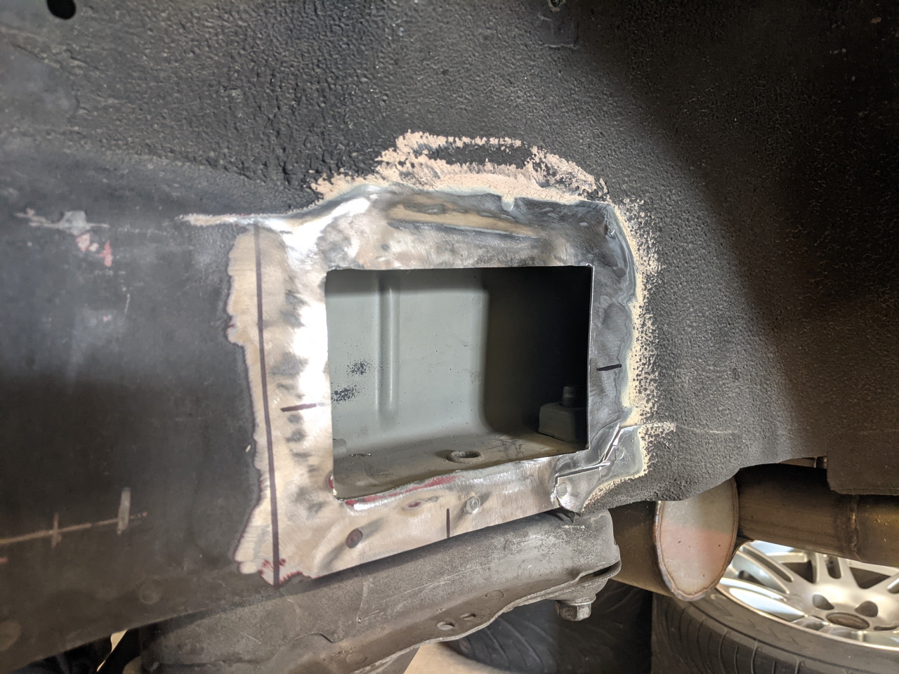
A little prep work around the cutouts, and marking the horizontal and vertical locations of the pivot point from my layout drawing. I had small notches cut into the box parts for alignment, since it's tough to locate the point in space where the center of the rod end will be otherwise. They will disappear once welded, just a tool for getting it lined up right at this point. Before installing I painted the back side of the boxes and then cleaned the paint off of the edges. I need to figure out some way to rust proof the inside of the frame where the welds will have burned the paint off, but so far I have not gotten there. The areas of the frame where the boxes attach are mostly (though as you can see not perfectly) flat. I did some hammer and dolly work on the frame in these areas before welding to get them as flat as possible. And with three corners of the box tacked, a little work with a hammer to bend that corner of the box in before welding helped close up the gap.
 |
 |
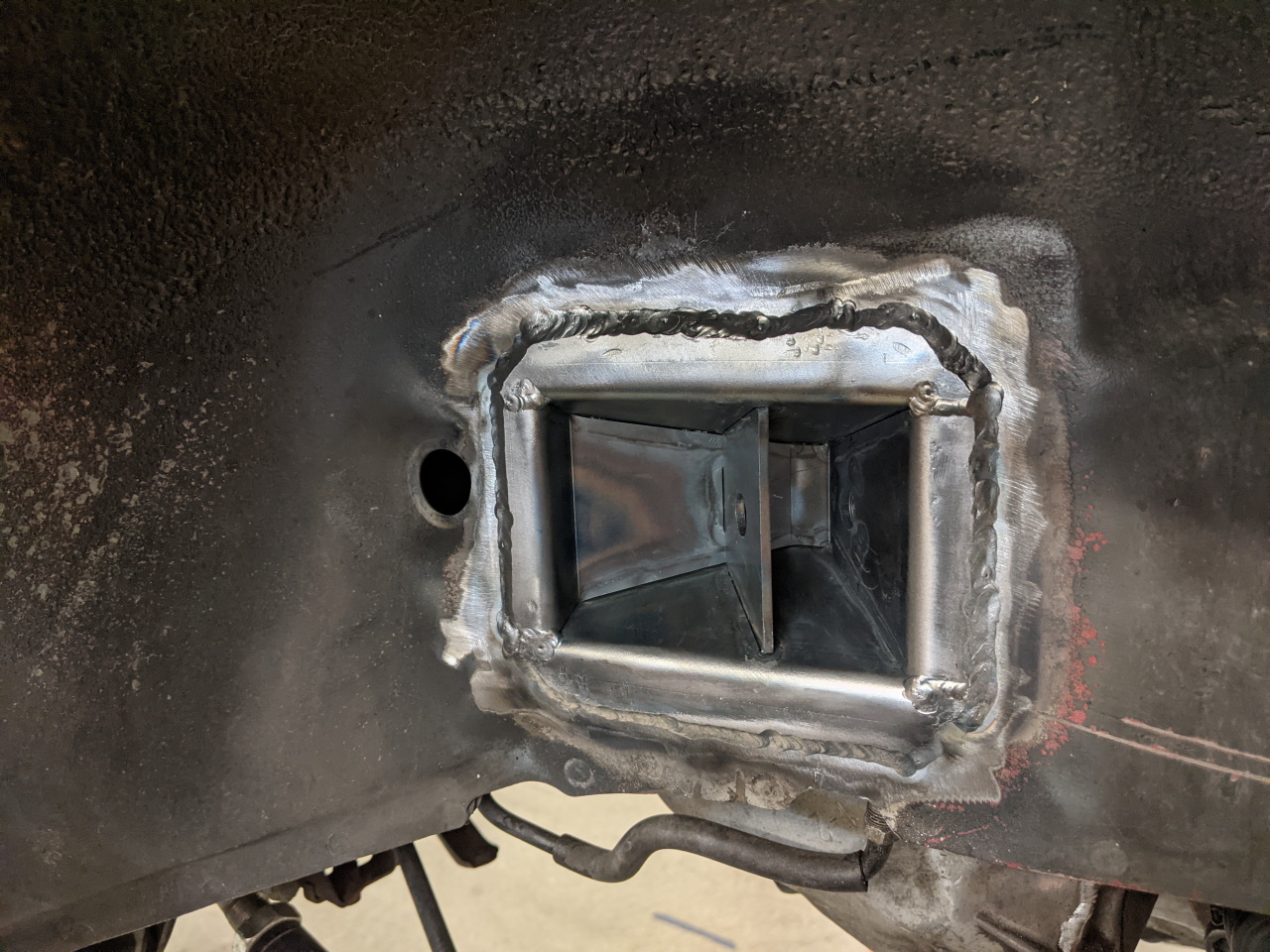
One last test fit with the boxes tacked in place to make sure there aren't any major problems before fully welding them.
 |
 |
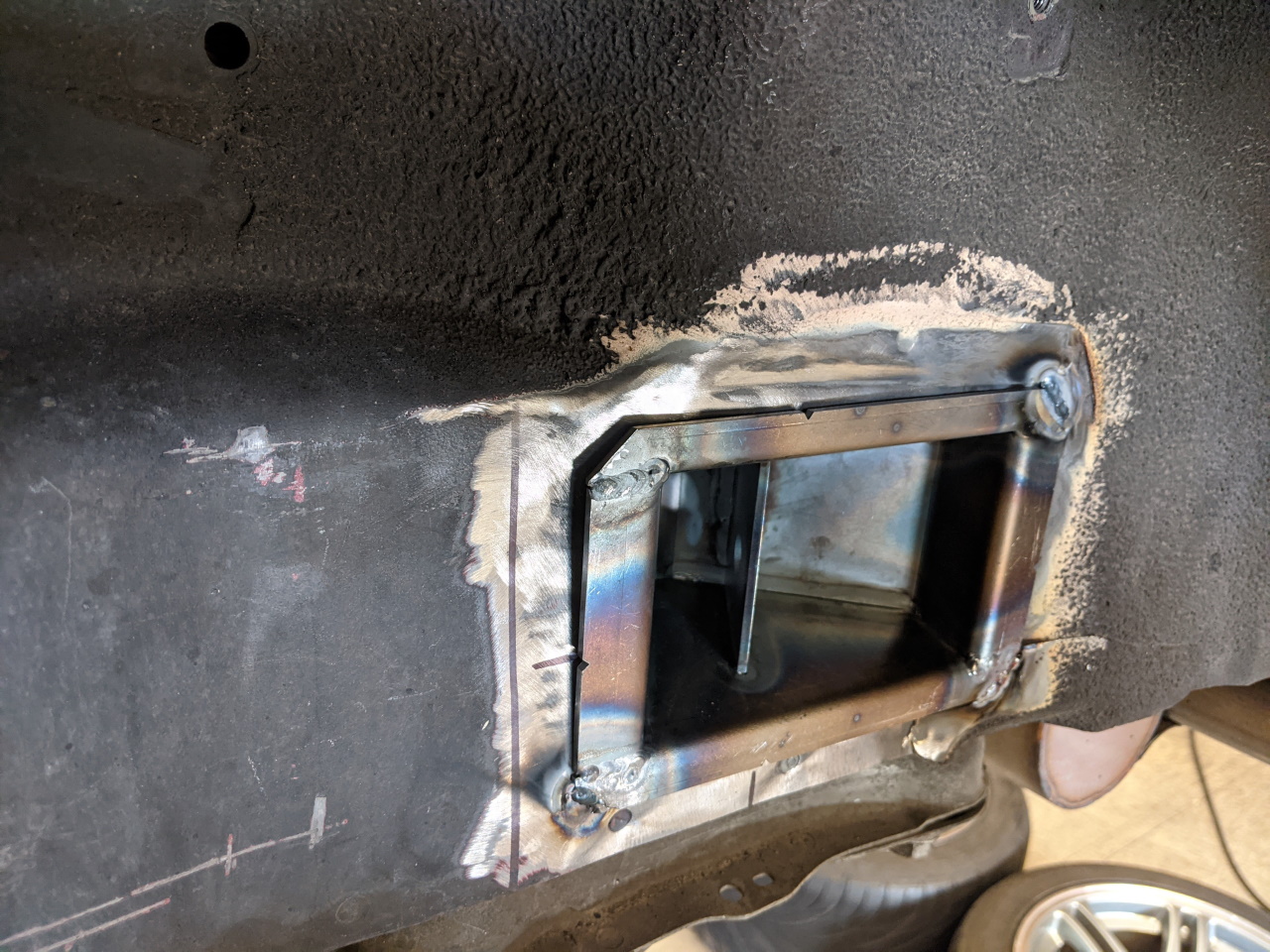
And with everything looking good, fully welded!
 |
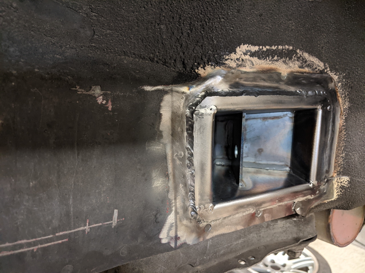 |
Remember those brake lines and ABS wires? For the brake lines, I was able to bend the stock hard lines a little so that the connection point the the flex line is a little further forward and a little lower, but otherwise in basically the same place. I drilled and tapped two holes in the flange of the box (it's not much, but it's thick enough to support a thread). If that thread ever fails I can always install a rivnut, but for now this will work. For the ABS wire I used a tubing bender to put two bends in the tube that holds the wire, and tapped another hole in the flange of the rear box. A new P-clamp to connect it to the cross member will finish it off (not yet done in this picture).
And now... we wait on the machine shop to finish the first set of knuckles as well as the A-arm adapters for the knuckles.
And wait.
And wait. It's OK. I needed to get the chassis to a point where I could verify the design a little better before I even ordered the A-arm adapters, so I expected there to be some delay here.
I didn't take any pictures, but I also made some bushings to adapt the lower strut mounting bolt down to fit the spherical bearings in the A-arm adapters.
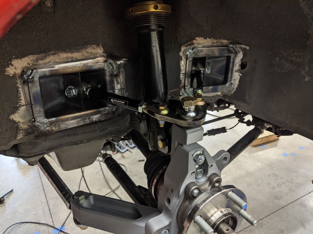
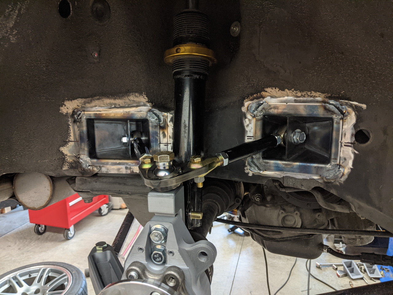
Setup and Finishing Touches
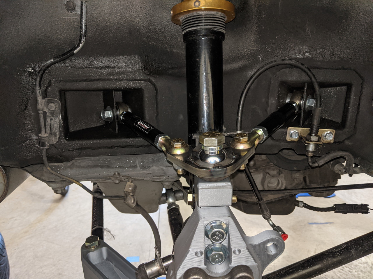
It took a while to get this all setup, adjusted, and aligned. Most of two days of tweaking, adjusting, checking bump steer, adjusting something else, checking bump steer again, etc. The forward / rearward inclination angle of the upright (what would be called caster on an axle with steering) is pretty important because it has a large effect on the toe curve, and any adjustments to camber using the upper arms also have the potential to effect this inclination angle. I found it best to get this set first and then to do most camber adjustment using the lower arms. Doing this with non adjustable control arms would be much more difficult. Also I ended up extending the lower arms some in order for my upper arm lengths to work, even at their minimum length.
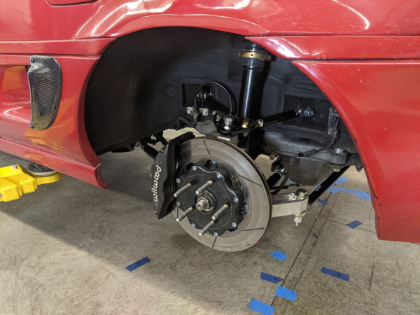
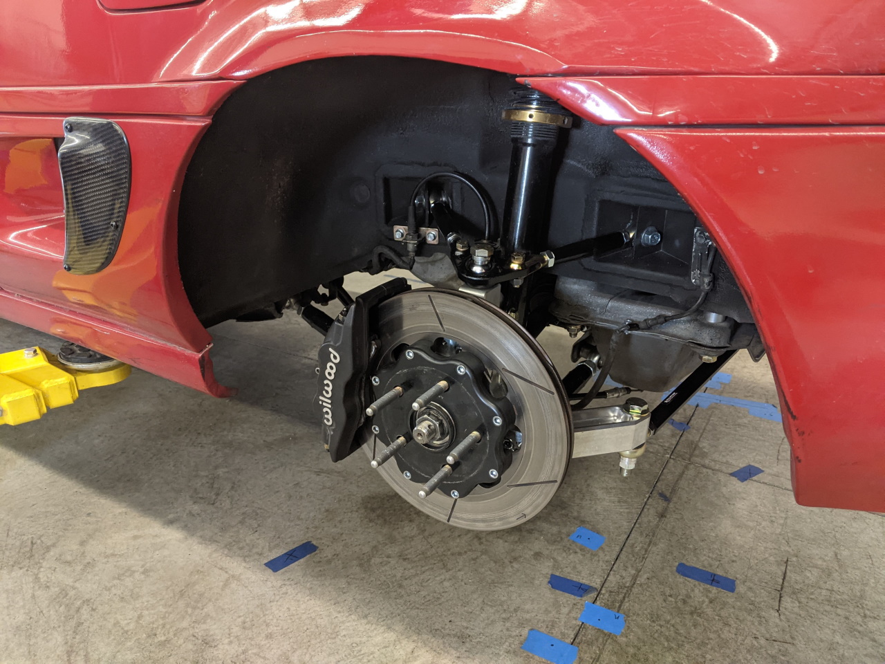
This resulted in a pretty aggressive fit on the rear wheels. Fortunately the improved camber curve means that they can stick out a little and still clear the fender on compression.
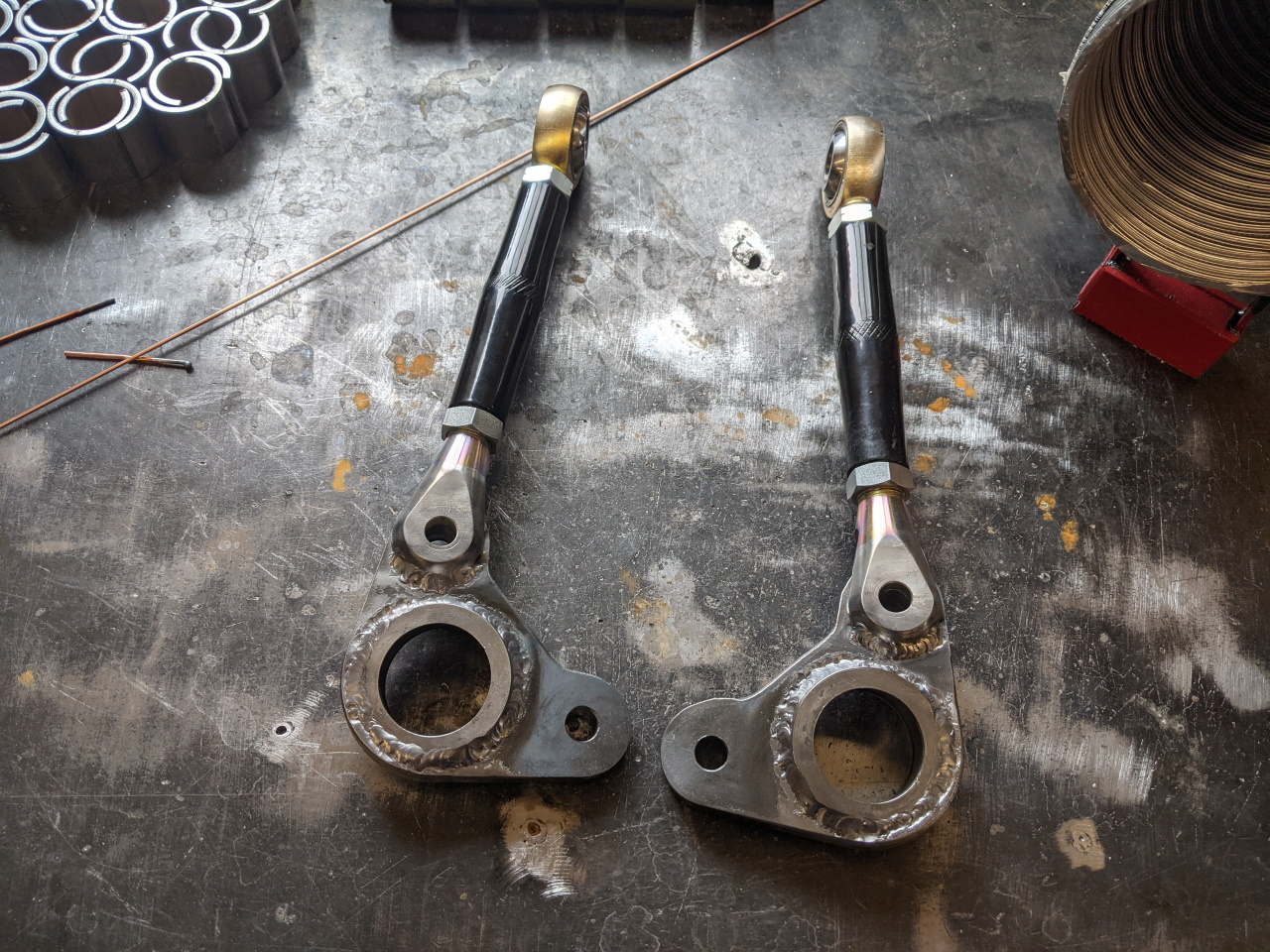
I also had to figure out the angle at which I wanted to weld one of the A-arm clevis fittings. The other must remain a bolted connection, as it needs to be disconnected to remove the arm from the car, but one of them needs to be rigidly connected. With that set the A-arm bearing cups and the clevises were welded, and that portion of the arm finished with a coat of paint. For a more production level part I would probably get these zinc plated, but this will do for now.
One last piece of the geometry puzzle. In order to avoid having an excessively high roll center, the design required that the rear cross member be lowered a half inch. I know you are used to me talking about roll centers being too low, but the A-arm conversion changes the situation some. For one thing, lowering the roll center no longer causes it to move around nearly as much as it does with the strut. For another, my goal here was to keep the rear roll center at or below the level of the front (same as it was with the strut), and without lowering the cross member it would have been several inches above the front roll center. In theory I could have also done this by simply reducing the height of my RCAs, but the problem there is I didn't have enough spacer to remove from the tie rod. Remember that the knuckles were designed to be used WITH the RCAs in place.
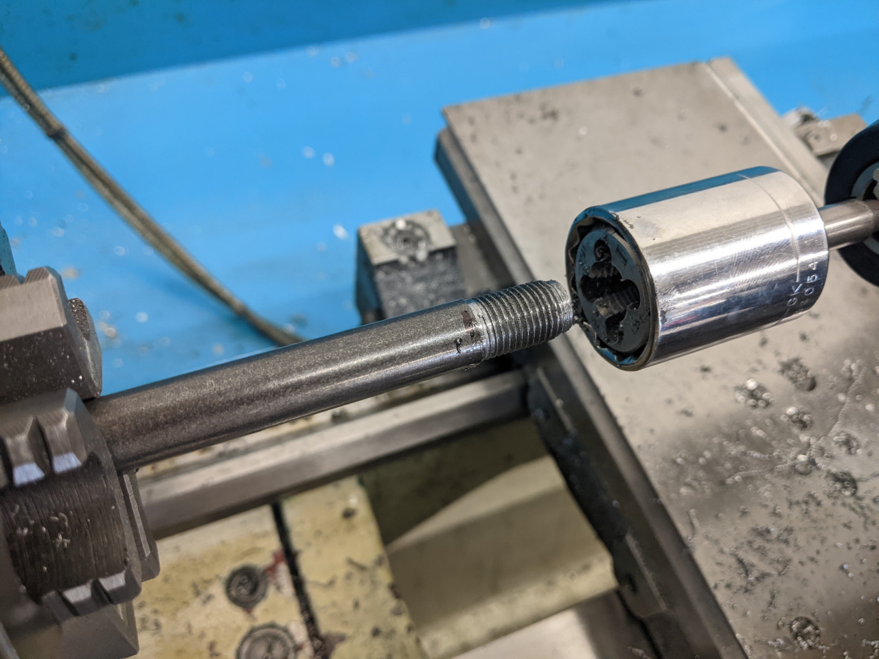
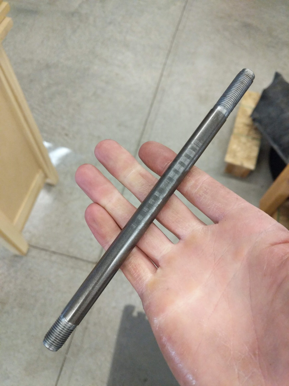
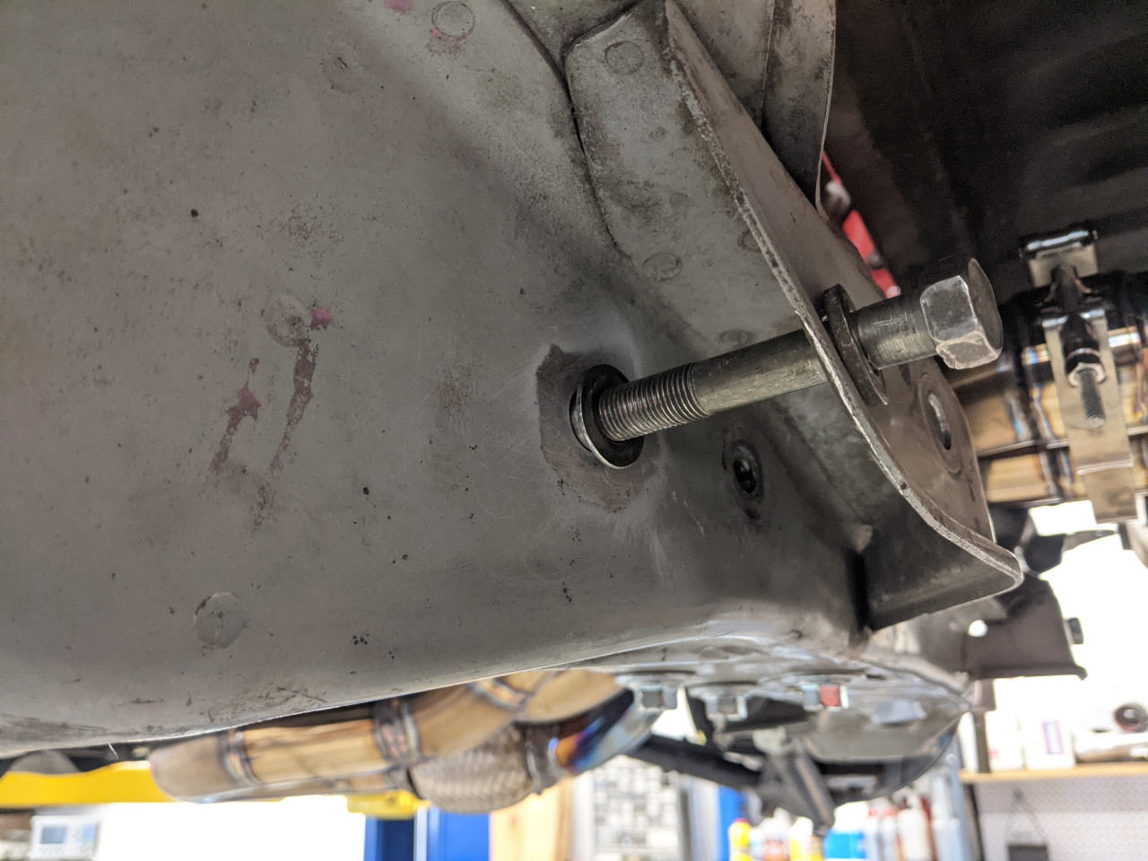
Fortunately lowering the cross member is pretty easy. Just some simple aluminum spacers for the four main cross member bolts, plus the three motor mount bolts. The shorter two cross member and the motor mount bolts are easy, just buy longer ones. But the front bolts are 190mm long, and longer ones simply don't exist (not that I could find anyway). So I made two custom M12 studs from some 1/2" steel rod.
 |
 |
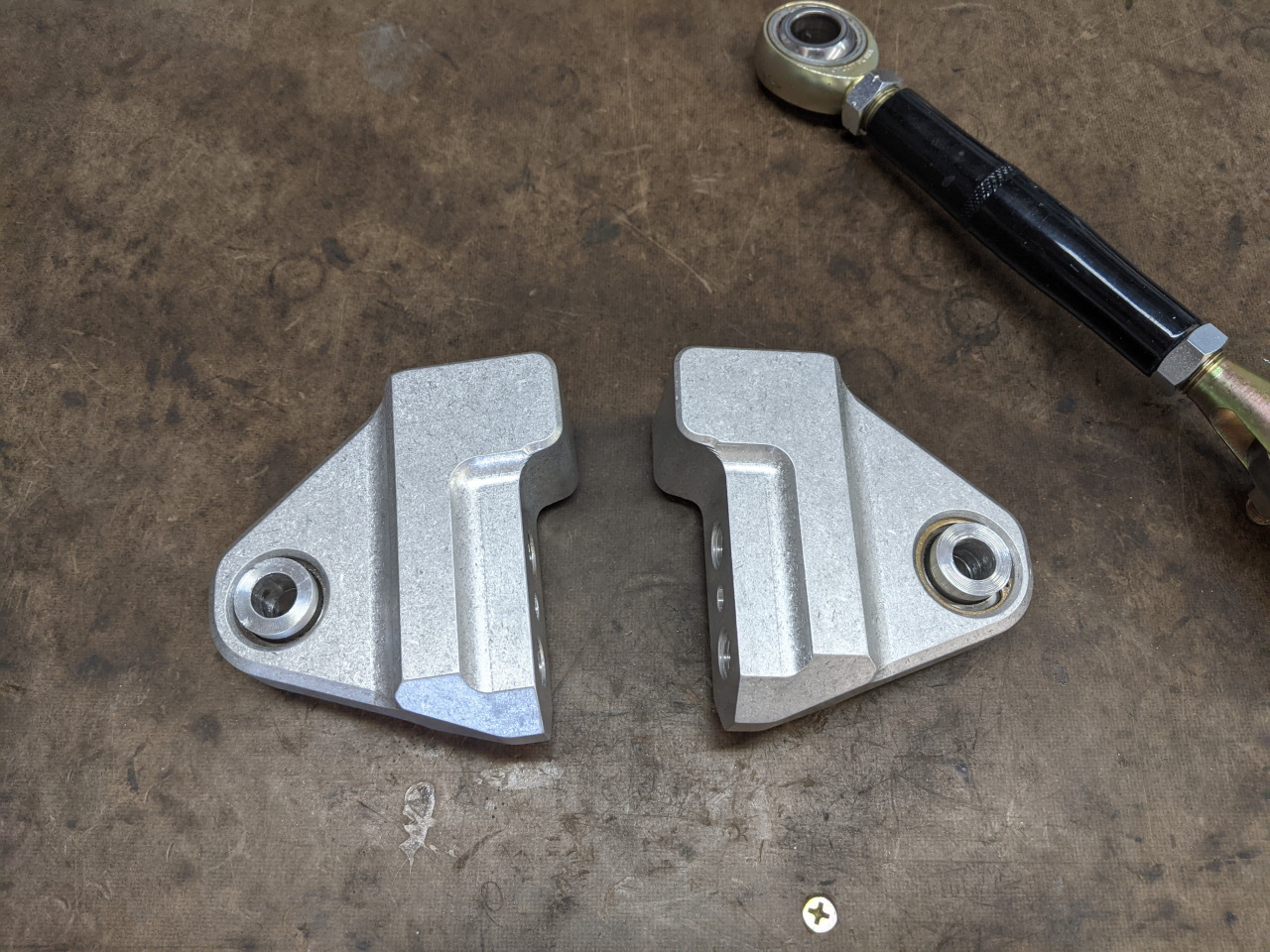
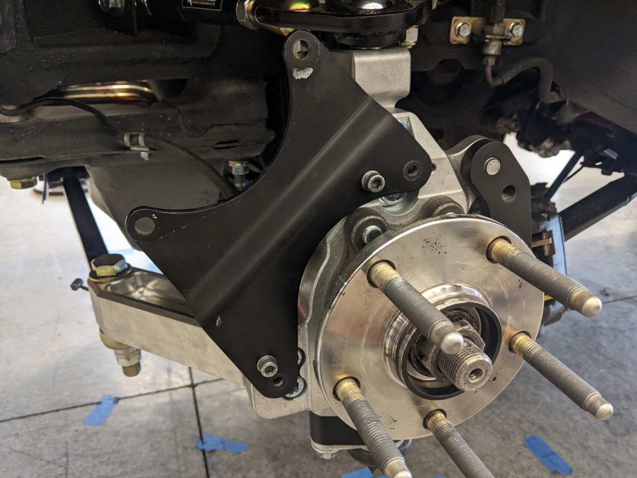
In order to fit my parking caliper, the parking caliper bracket had to be modified. I was expecting this. You may have noticed in pictures of the knuckles that they have two small threaded holes at the top. One is for the parking caliper in it's normal position, the other was to allow it to be clocked rearward to provide clearance for the A-arm or multi-link conversion. I used a paper template to locate the holes (printed from a drawing created from my 3D model), and drilled two new holes in the bracket.
I mentioned previously that I planned to try the toe curve that resulted from using the stock toe rod point on my 91 cross member, but I kept thinking that it was just more dynamic toe than I really wanted. The car drove well (although I had not had it on a track or autocross course yet), but in the past I have found that reducing the amount of dynamic toe was helpful in improving both handling and tire wear. That and I have always felt that while Toyota had the right idea with the change to the toe curve on the Rev2 (93+) cars, I think they took it a bit too far. To reduce the amount of toe change, I need to move the tie rod attachment point out, and as a result shorten the tie rod. I started with a pair of templates made out of some scrap aluminum. By drilling the holes in the templates at the same time I ensured that I was moving each point by the same amount relative to the stock point. In this case, I settled on 2.25 inches.
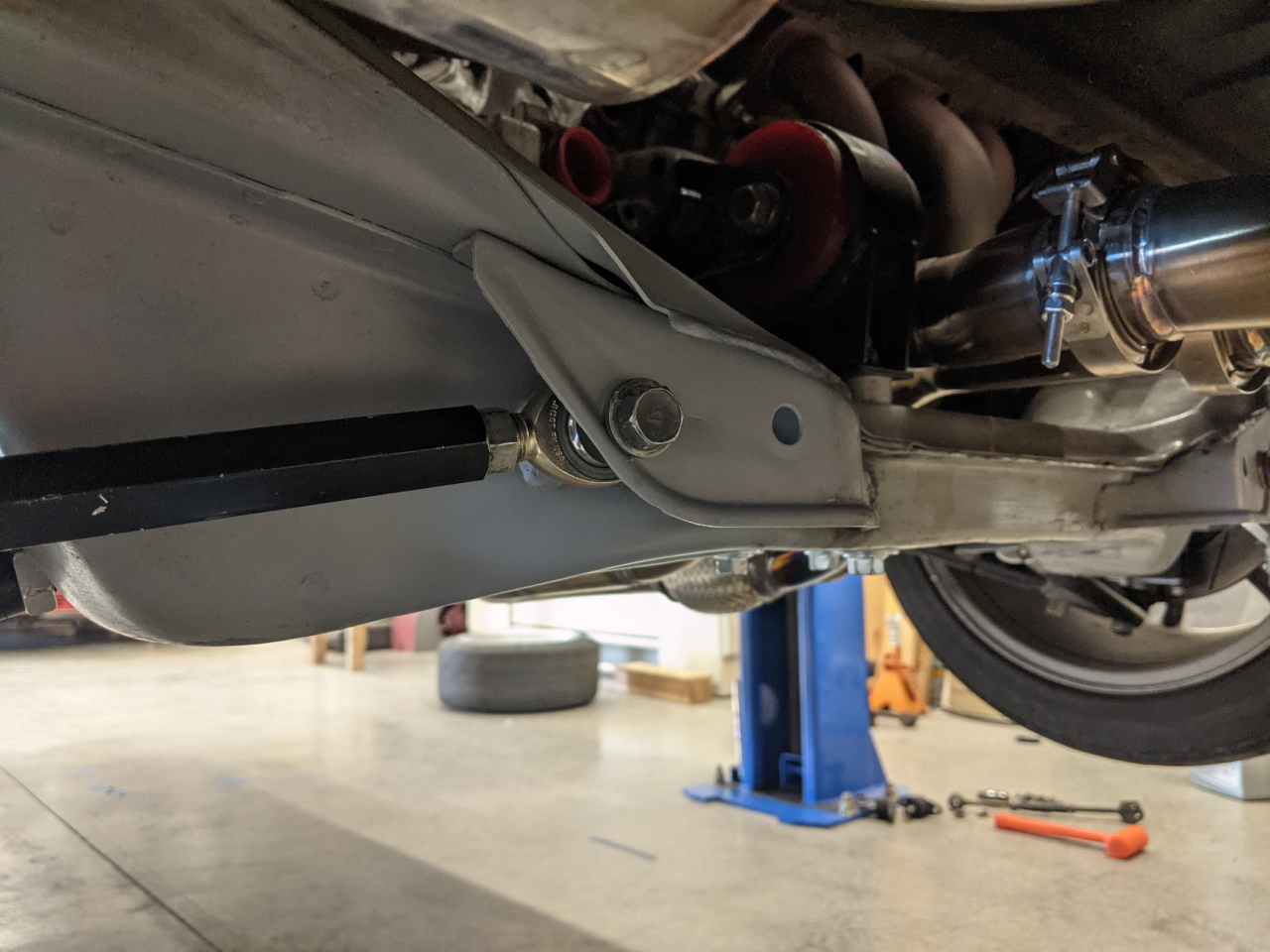
With the holes drilled I used a bolt to align the threaded insert (made from a modified nut) to be welded into the cross member. Due to the angle of the cross member there is a substantial gap that will need to be filled, but that's not too difficult.
Weld the nut in place and finish it up with some paint and a shorter tie rod!
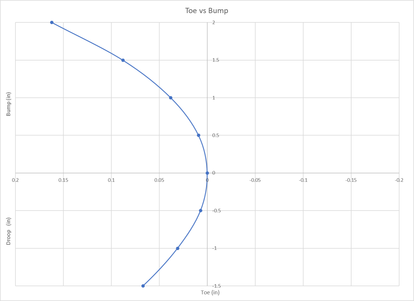
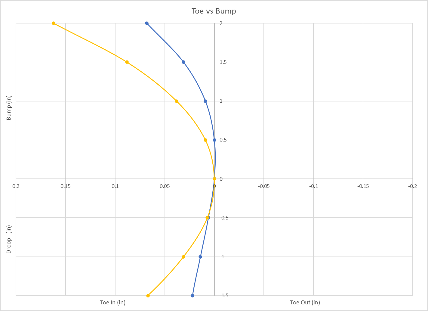
What this gives me is the toe curve shown below in blue, compared to the old one in yellow. Still some toe in on both compression and rebound, but substantially less. And, I can easily go back to the original point if I feel I need to for some reason.
And that's about it. Except of course for a whole lot of testing to come, fingers crossed that nothing breaks! At this point I have driven the car maybe 150 miles with the conversion, but I will update this post as I put more miles on it and am able to offer more thoughts on the results of the change.
Testing
About a month after finishing the conversion, and with a few hundred street miles on it, I hit the first local autocross to give it a real test. For a setup that was completely theoretical and used the same spring rates as I had used previously on the strut, the results were quite dramatically good. A little more over steer than I generally like, but easy to drive and I was able to mostly tune out the over steer with damper settings. I may increase the front spring rate a little, or I may first try just raising the front ride height a little (and therefore raise the front roll center). Here's a video of my fastest run of the day.