For years my suspension has been basically all of the parts that I sell, but not much of it was unique. Standard geometry kit, Koni coilovers with my top mounts, the control arms were the only "custom" pieces. Spring of 2020 I found myself with some extra time on my hands, and I seriously revisited my suspension model for the first time in years. Maybe I can improve things a bit...
I purchased a license of SusProg3D a couple of years ago, but other than getting the basic suspension layout modeled I hadn't made much use of it. It's a pretty good program and very powerful, but the learning curve IS a bit steep! What I found once I started analyzing the model of my current suspension was that I had been running the car too low recently. The roll centers were a bit lower than I would like, and as a result were moving around a lot more than I like to see. And while there is a certain school of thought that says kinematic roll centers aren't all that meaningful, I still feel that they are a good indicator of the overall state of the suspension design. In my experience large roll center movements have a destabilizing effect that you can feel as the driver. The question is, what can I do to improve things. Without just raising the car, that would be too easy!
Rear Suspension
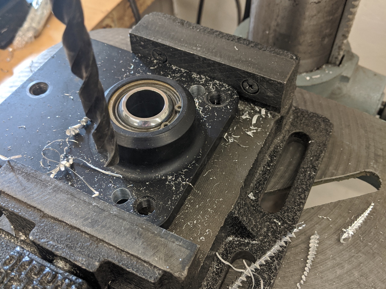
One thing you can do to improve the geometry of a strut suspension is tilt the strut further in. My top mounts already do this, but I decided to take it to the next level. There was just enough room on the inside to move the top of the rear strut in another 1/2", so I took the rear coilovers apart and drilled and tapped two new mounting holes in the top mounts.
 |
 |
Upon test fitting, I found that the edge of the plate was now hitting the radius at the top of the strut tower, so I added a chamfer with the belt sander to clear.
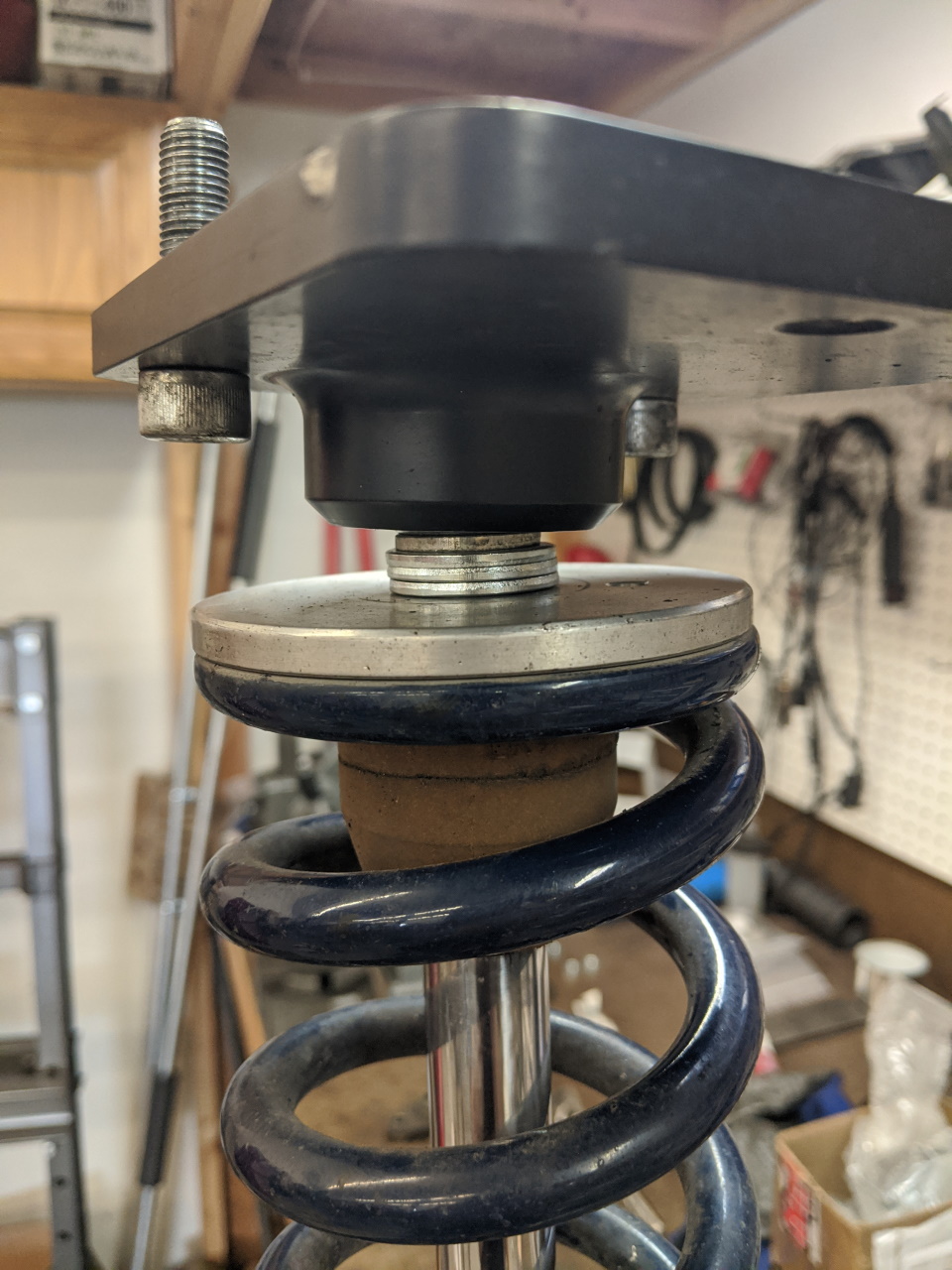
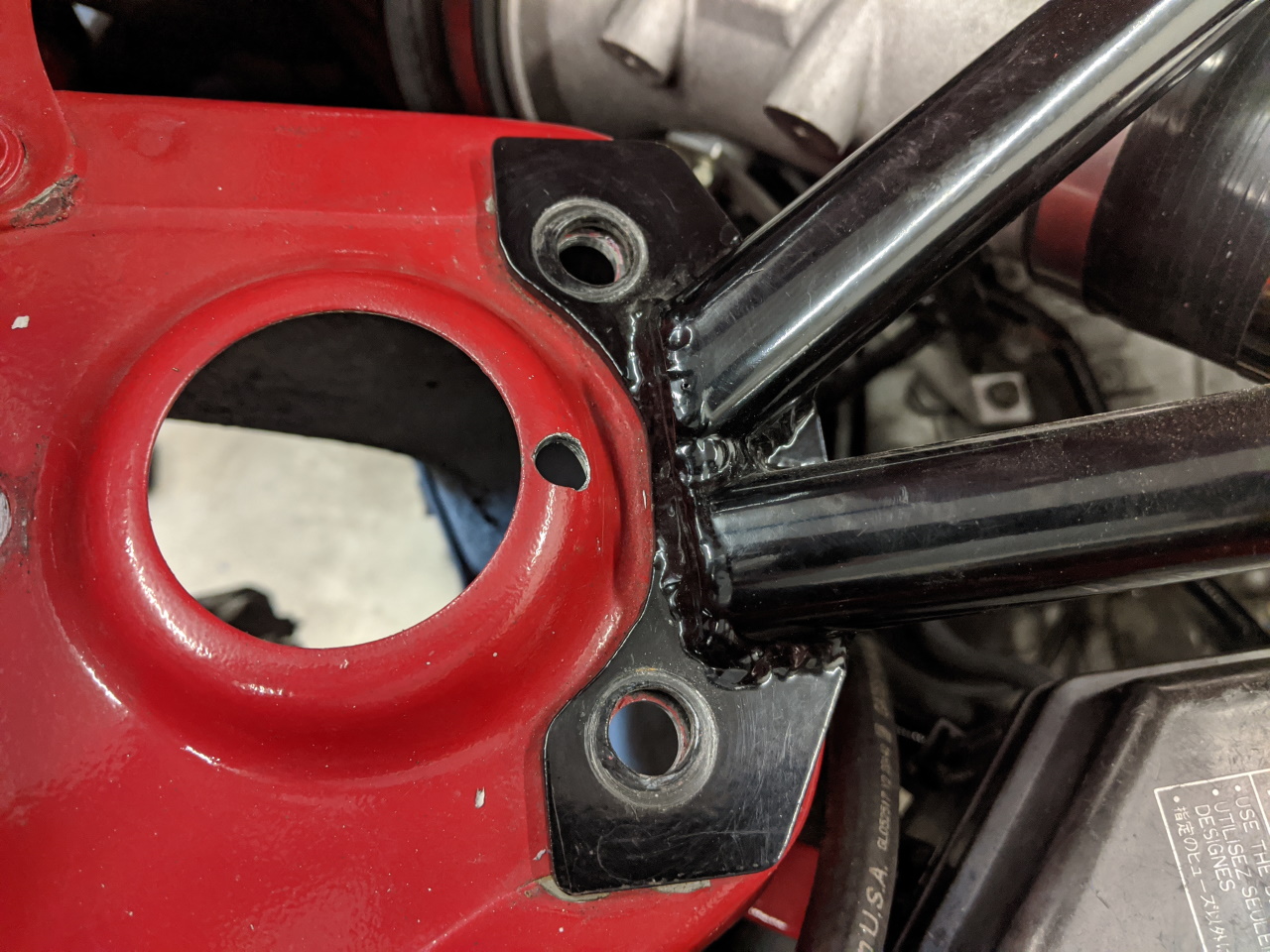
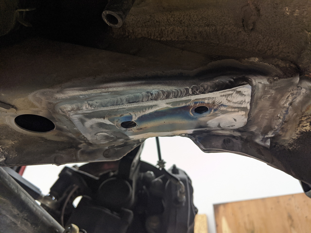
Re-assembling the coilover and test fitting again revealed another problem. The spring perch was contacting the raised area in the chassis shown below.
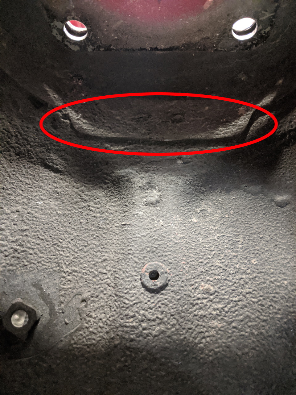
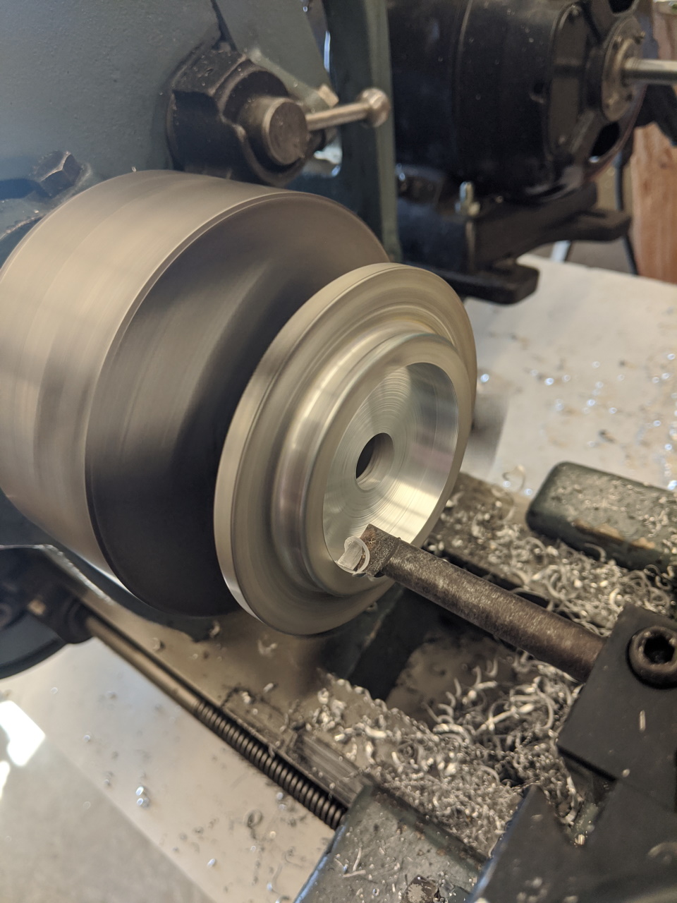
It appeared that this could be solved by moving the spring perch down a little, but there isn't enough thread on the top of the Koni struts to simply add spacers between the perch and the top mount. So I bored out the bottom of the spring perch on the lathe, allowing me to add 1/4" of spacer (washers) and keep the same total stack up height of the spring perch, spacers, and top mount.
 |
 |
That solved all of the fit issues (a coilover with 60mm springs probably wouldn't have had this problem), but I still only had two of the three mounting bolts, and the plate wasn't large enough to add the third. I'm sure you can guess where this is going.
 |

|
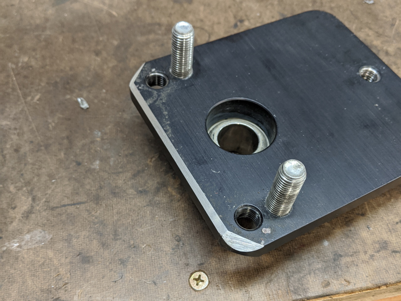
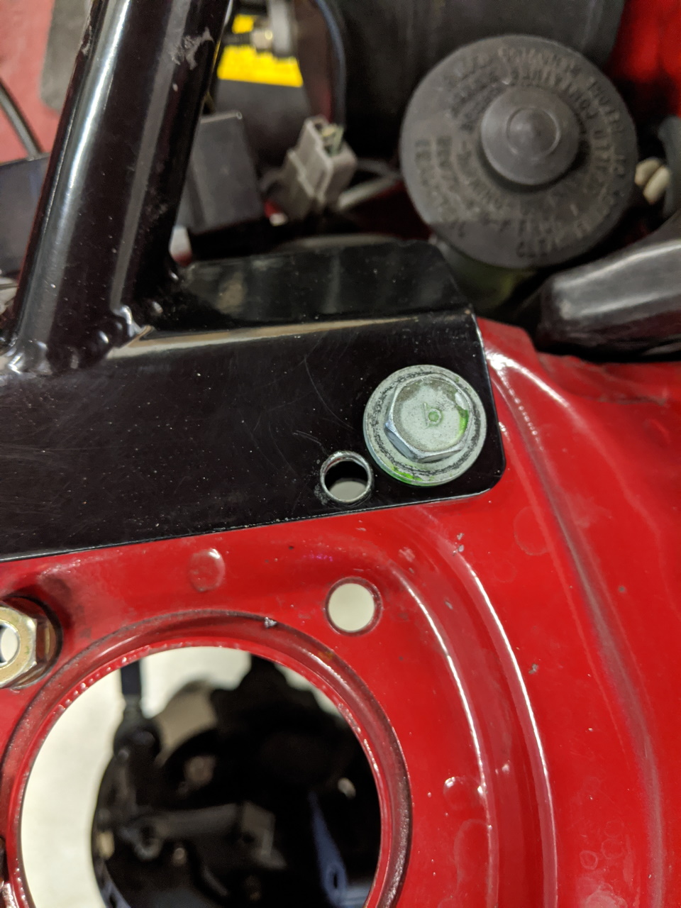
And here is the complete rear plate with the third fastener installed.
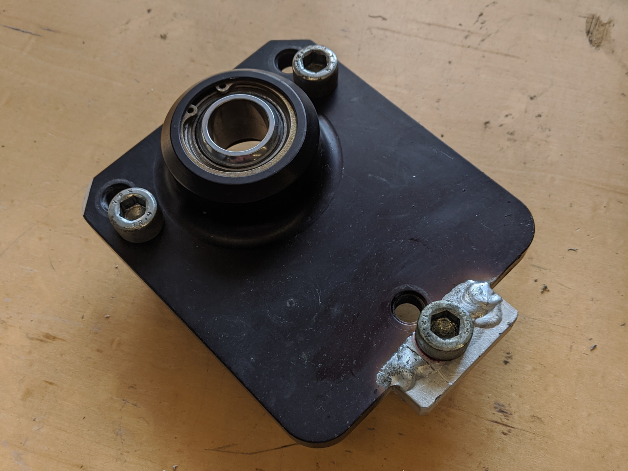
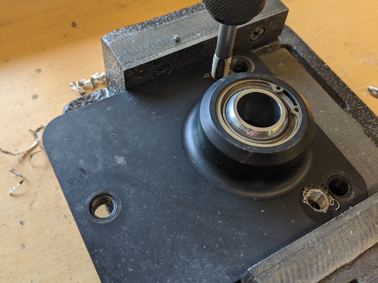
To access the adjuster, a little chassis modification was required.
Of course tilting the strut in like this added static camber. I was using two stock size knuckle bolts in the rear, and between the top mounts and the slightly longer than stock control arms I had about -3.5° of camber. To get back to that point all I had to do was put a 3-dot Toyota crash bolt in the top hole and pull the camber as far positive as it would go.
Front Suspension
On the front, the steps to modify the strut mounts are all the same except that I shifted it by 3/4" instead of 1/2" (there is more room in the strut tower to move it further inboard). And of course, just like the on the rear a new hole is needed to access the adjuster.
|
|
|

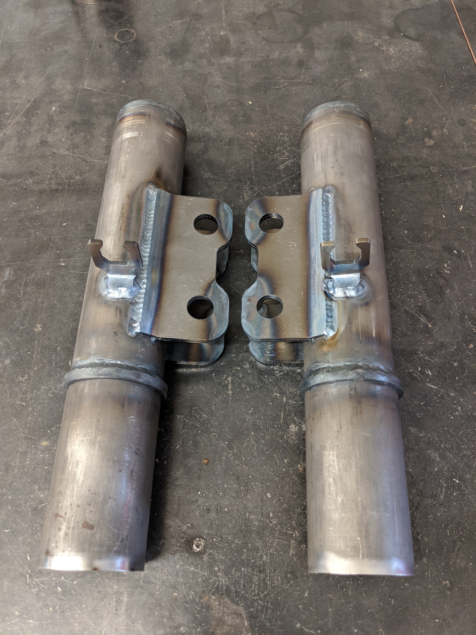
With the front strut leaned in an additional 3/4" at the top, the extended knuckle bracket that I put on my coilovers was no longer necessary to clear the wheels and tires. This feature was always a bit of a compromise as it does have a minor negative effect on the suspension geometry, but helping to fit wider tires is worth it in my opinion. So I built a new set of front strut housings using knuckle brackets normally used on the rear. Loyal readers have seen this process before, so I won't go into detail. But, here's a quick shot of the finished housings.
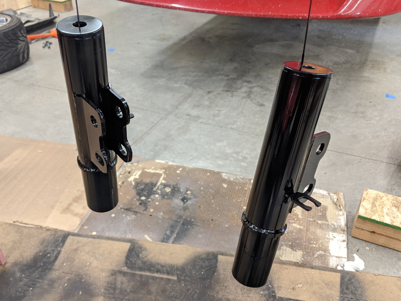
Well, almost finished. At this point I had something like -6° of camber, even with a 3-dot crash bolt set to full positive. Smaller bolts weren't an option in this case, too much adjustment was needed, so I decided to slot the top hole on the strut. With that done there wasn't much material left, so I built it back up with several weld beads and then ground it down flat on both sides. A quick coat of black paint finished them off. Maybe next winter I will get them powder coated.
 |
 |
Suspension Analysis
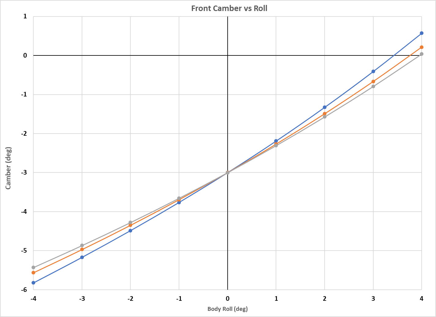
So, what did all this do for me? Let's start with the front, since that's where I made the largest changes, and also where the roll center behavior was worse to start with. Blue is the original, orange is from modifying the top mount, and gray is the result of the new strut housings. The camber curve is improved quite a bit, gaining 0.6° of camber at 4° body roll. I know it doesn't sound like much, but with a strut suspension, you take what you can get!
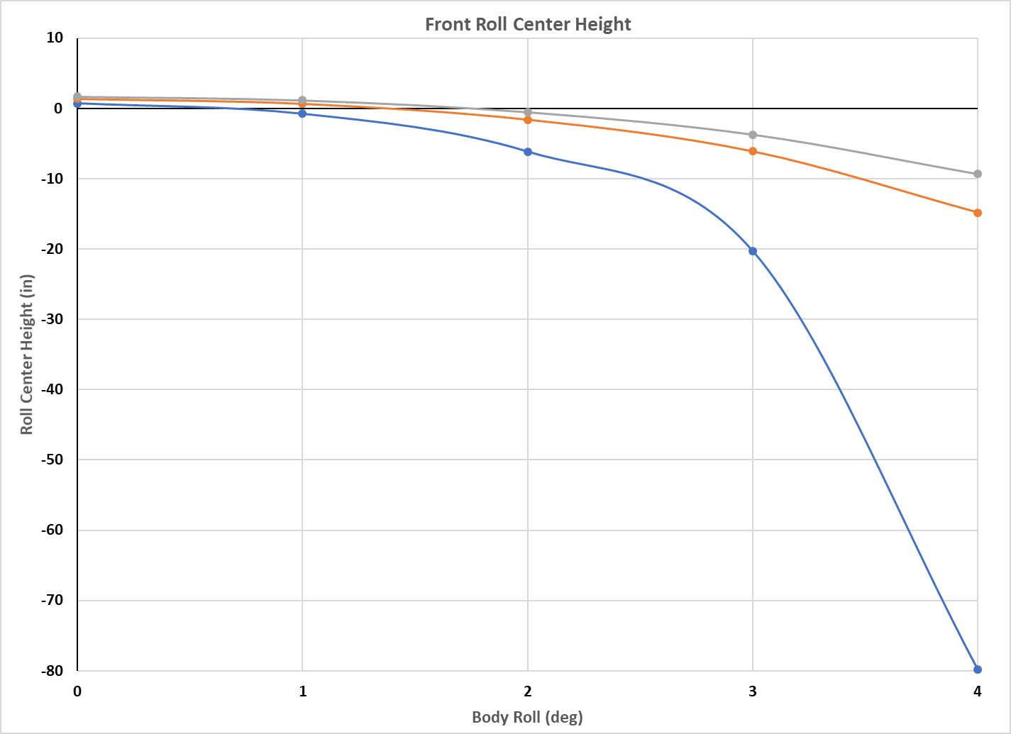
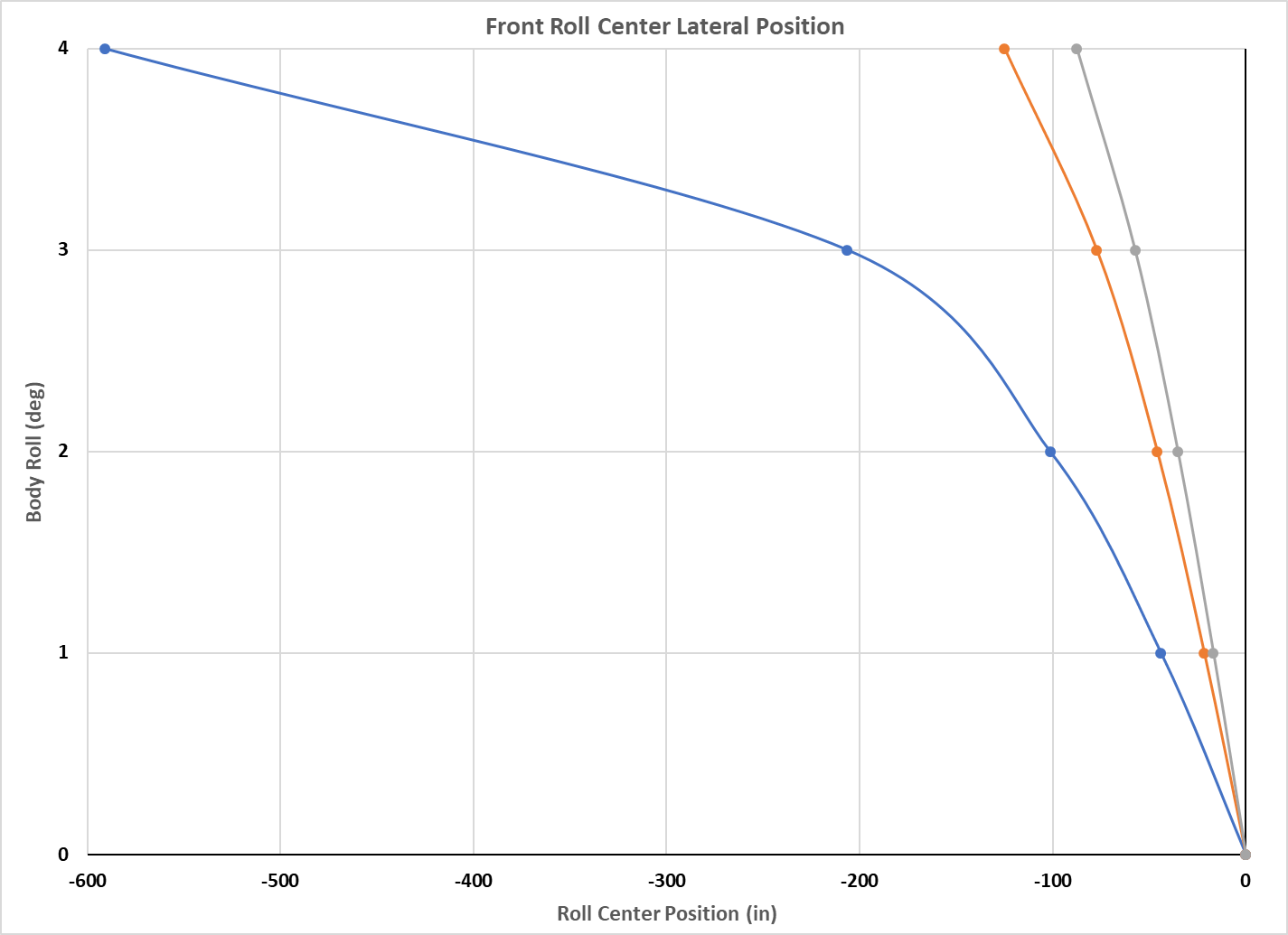
The roll center is raised by 1" at 0 roll, and it's movement is dramatically reduced both laterally and vertically. In theory, allowing the front roll center to drop like that causes the front roll stiffness to decrease as body roll increases. This would tend to cause over steer at the limit, or would require one to setup the car with more front roll stiffness than needed in order to balance it at the limit. Hopefully by keeping the front roll center under control the entire car will behave a bit better.
You might ask, what about negative side effects? By tilting the strut in, I have increased KPI (King Pin Inclination), also known as SAI (Strut Axis Inclination). It is now at about 20° on my car, and caster is about 7°. And while this is a lot of both by most standards, it is not without precedence. From what I have been able to find, this is similar KPI to what Porsche is running on their GT3 Cup cars, and actually a little less caster. If you look at the pictures here, visually it appears that they have a LOT of both caster and KPI. And if you are trying to make a strut suspension work, one can certainly do worse than to copy what Porsche is doing on their factory race cars.
The side effects of both caster and KPI are increased jacking effects. Jacking is an effect where turning the steering causes the front wheels to rise / fall, causing weight to be transferred from one wheel to another. The interesting thing is, the jacking effects of caster and KPI are roughly opposite of each other. So they tend to cancel each other out on one side of the car, and add to each other on the other side. Below is the jacking effect on my car before and after the new revisions to the front suspension.
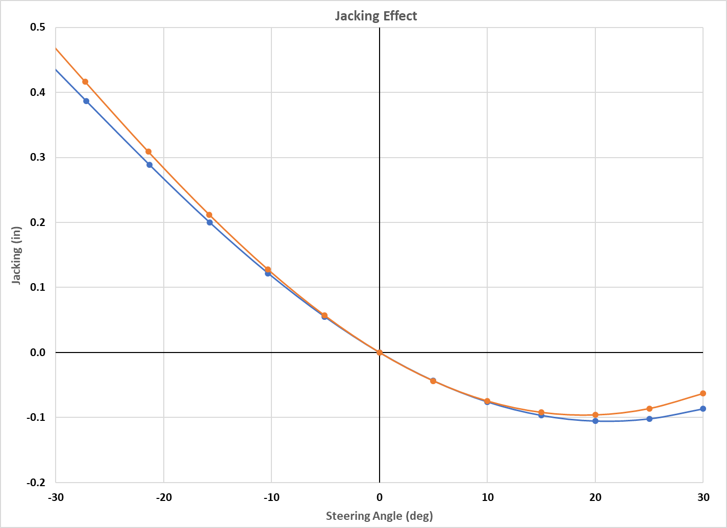
This is considering the left front wheel, with negative steering angle to the left, and positive steering angle to the right. What this means is that at 20° of steering angle the outside wheel (in a corner) has been pressed down 0.1" into the road and the inside wheel has been lifted about 0.3" up. When cornering hard the inside front wheel is quite often off the ground anyway on the MR2, so lifting it a little more probably isn't going to hurt much. And the overall change in jacking effect induced by the modifications described here is relatively minor. The car worked well before, I doubt this is going to ruin things.
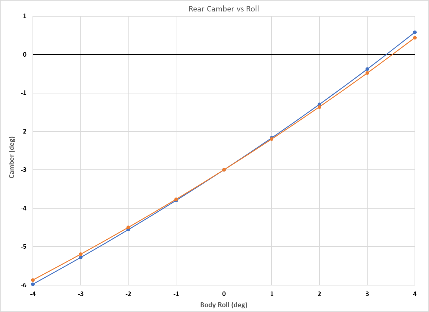
On the rear the improvements aren't quite as impressive, but the changes were less dramatic as well. The camber curve is improved slightly, about 0.2° more camber at 4° body roll.
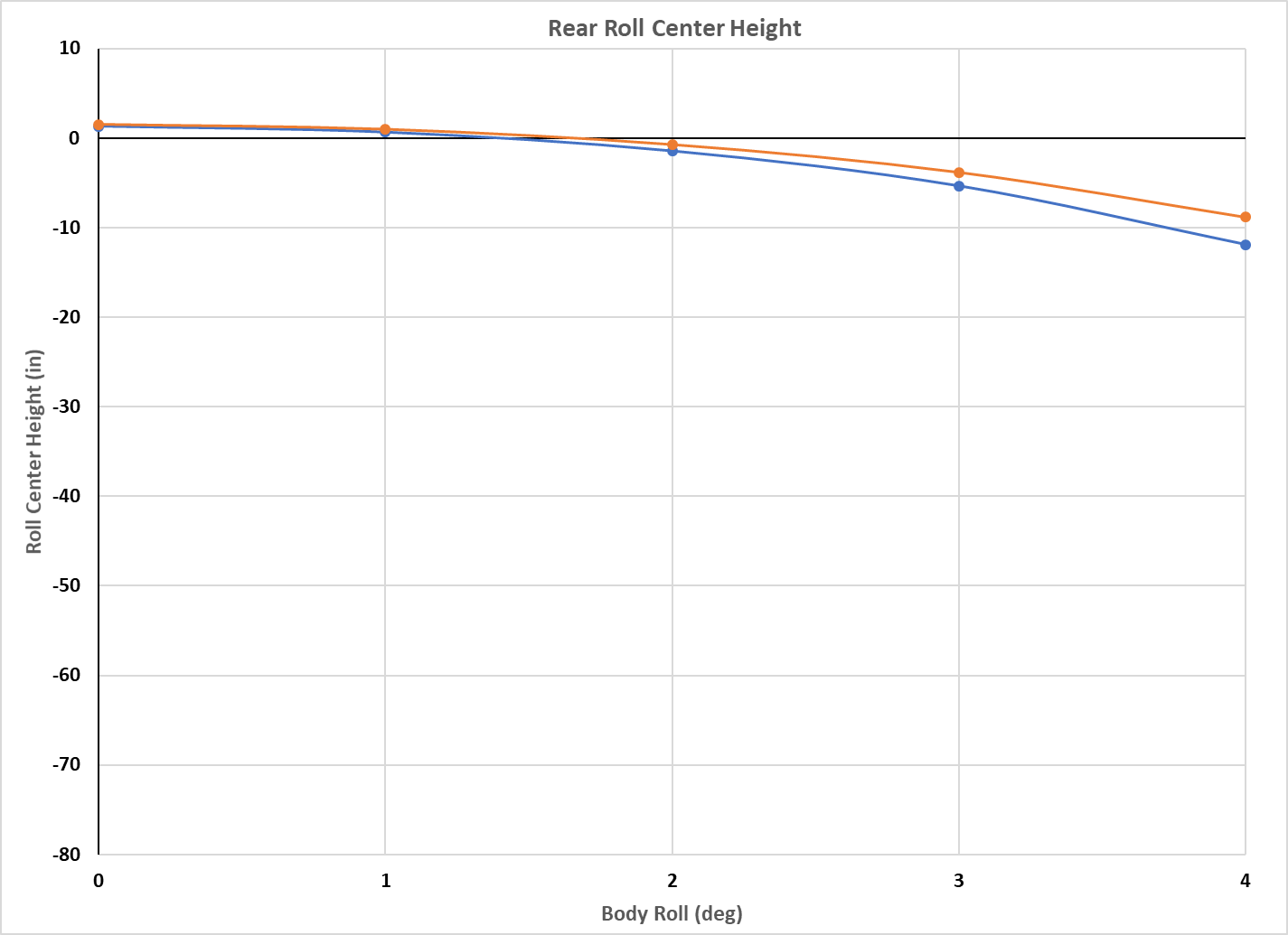
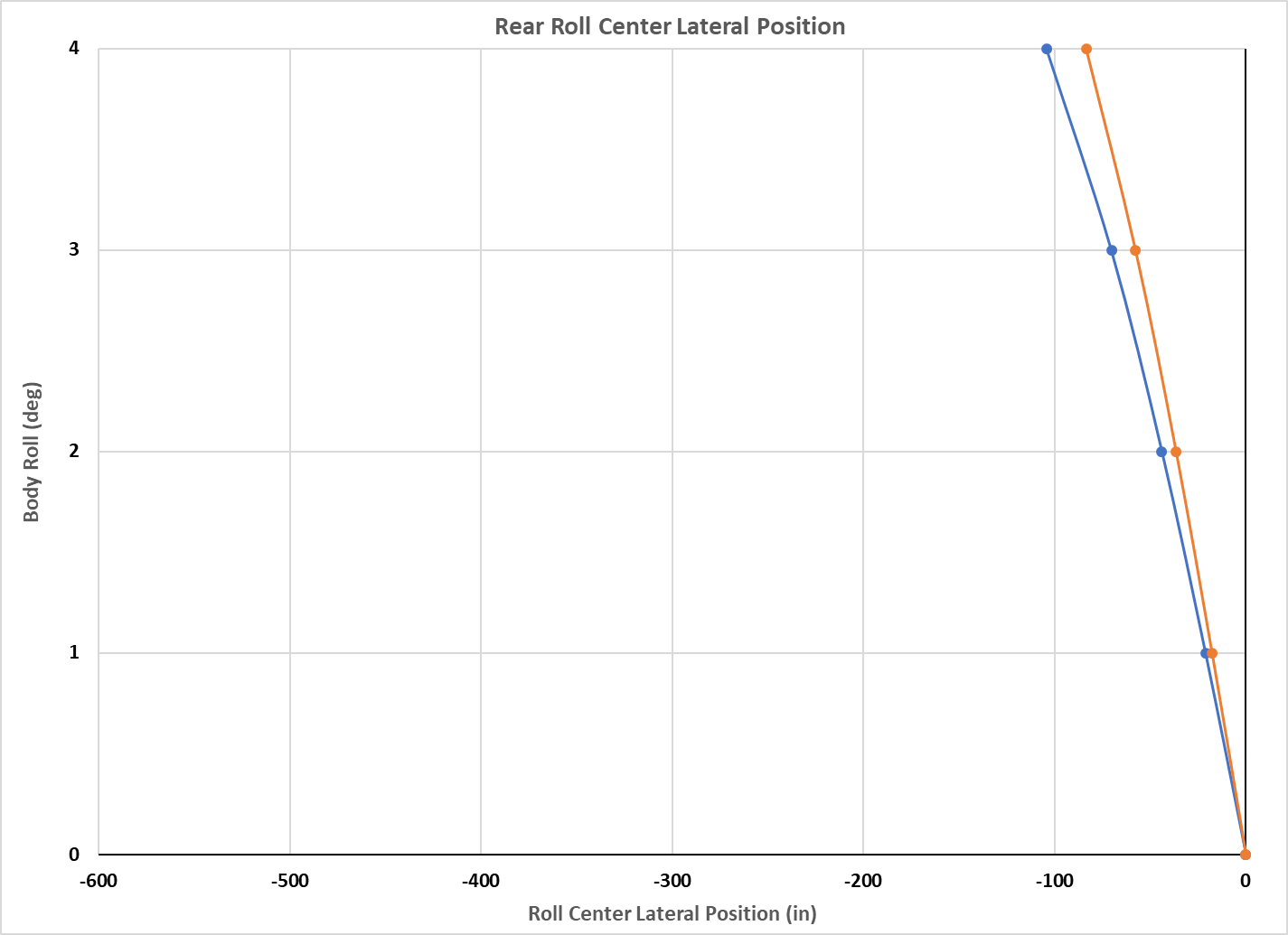
The roll center is raised very slightly, about 0.2" at 0 roll. However at 4° roll the roll center has raised about 3" and moved laterally by 21" less. Put another way, that's a 20% reduction in roll center movement, and that was my primary goal here. These graphs are plotted at the same scale as the front to make them easier to compare, though obviously the full range is not necessary here.
Sway Bar
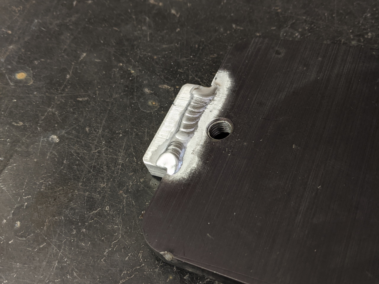
While I was working on this project, I was reminded that I have always found the standard bolt-on sway bar reinforcement places to be a little clunky. Quite possibly overkill. I think I can do better. This piece of 1/8" steel plate welded to the chassis should do the trick.
On the subject of the sway bar, you may have noticed that I didn't put sway bar brackets on my new strut housings. You did notice that, right? That's because last year I built a custom front sway bar which I attached to the control arm instead of to the strut. I just never actually got around to writing about it until now. That project started with the addition of a tab on the front control arms.

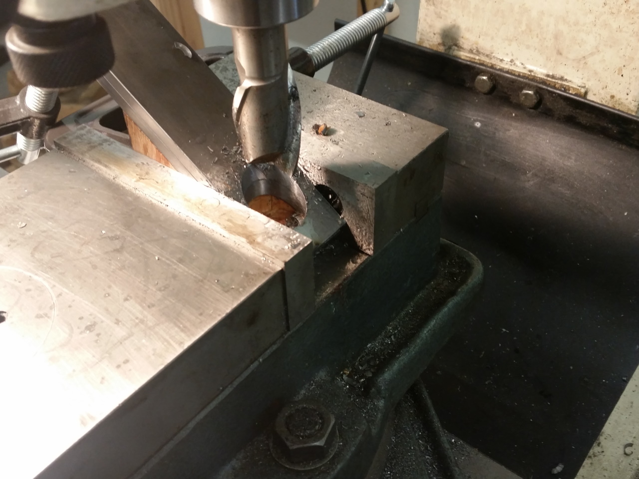
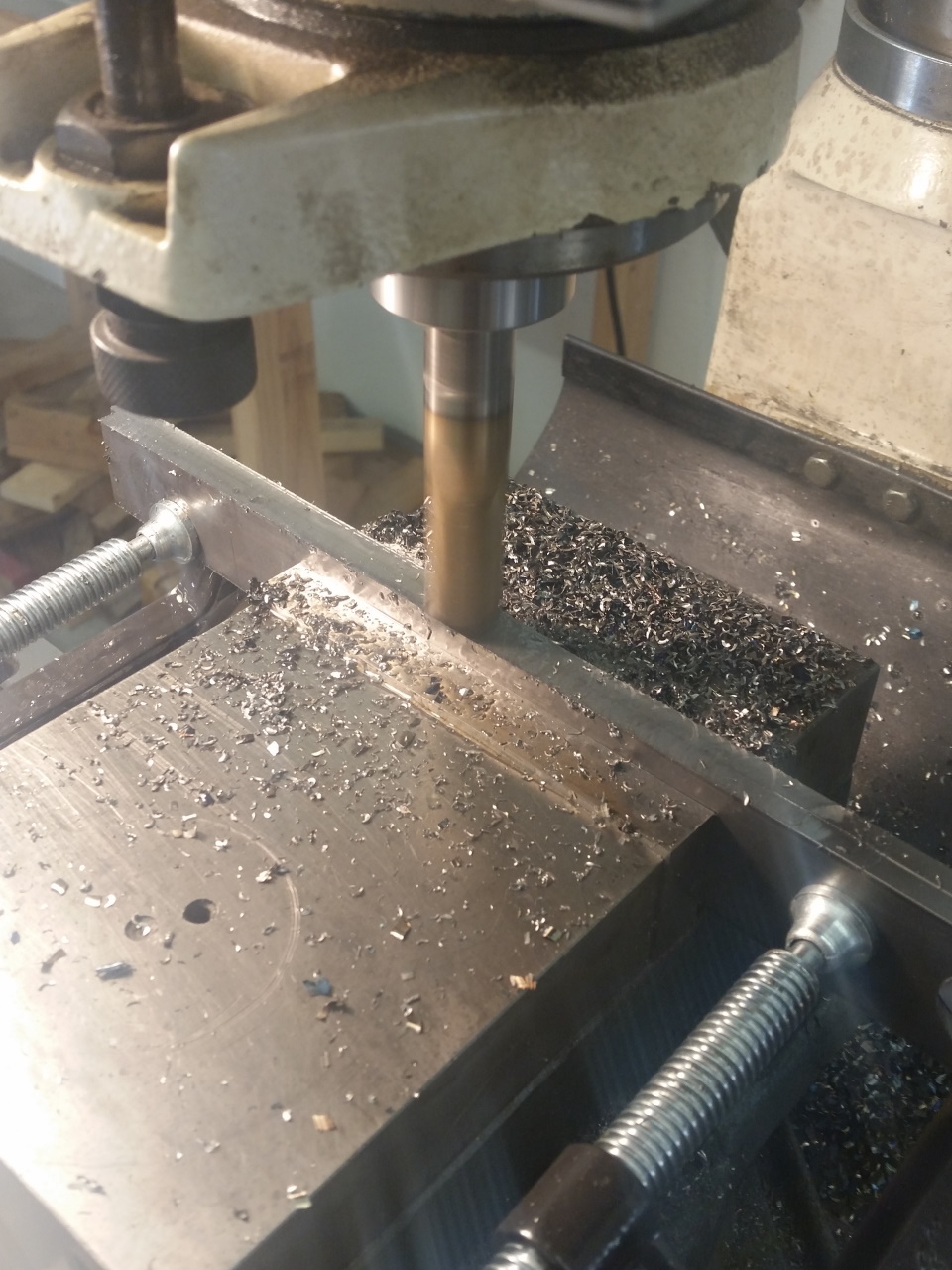
For the bar itself, I started by boring a 1" hole on a diagonal through pieces of steel plate, destined to become the arms of the new sway bar. Next I clamped them in the vice on edge and at an angle so I could machine a taper along their length. Last they were bent (which sadly caused them to crack), and welded back together on the crack. I didn't take pictures of that apparently.
 |
 |
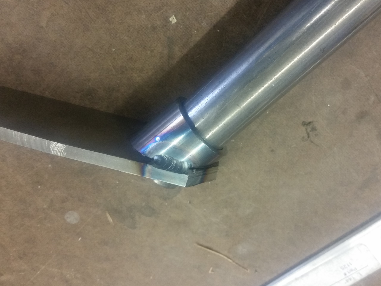
A short piece of tube with an angle cut on one end slips over the main sway bar tube to keep it centered between the bushings and to gusset the joint between the tube and the arms, and all of the joints were fully welded. Here it is finished up with some paint, and installed with some universal 1" sway bar bushings and custom short end links.
 |
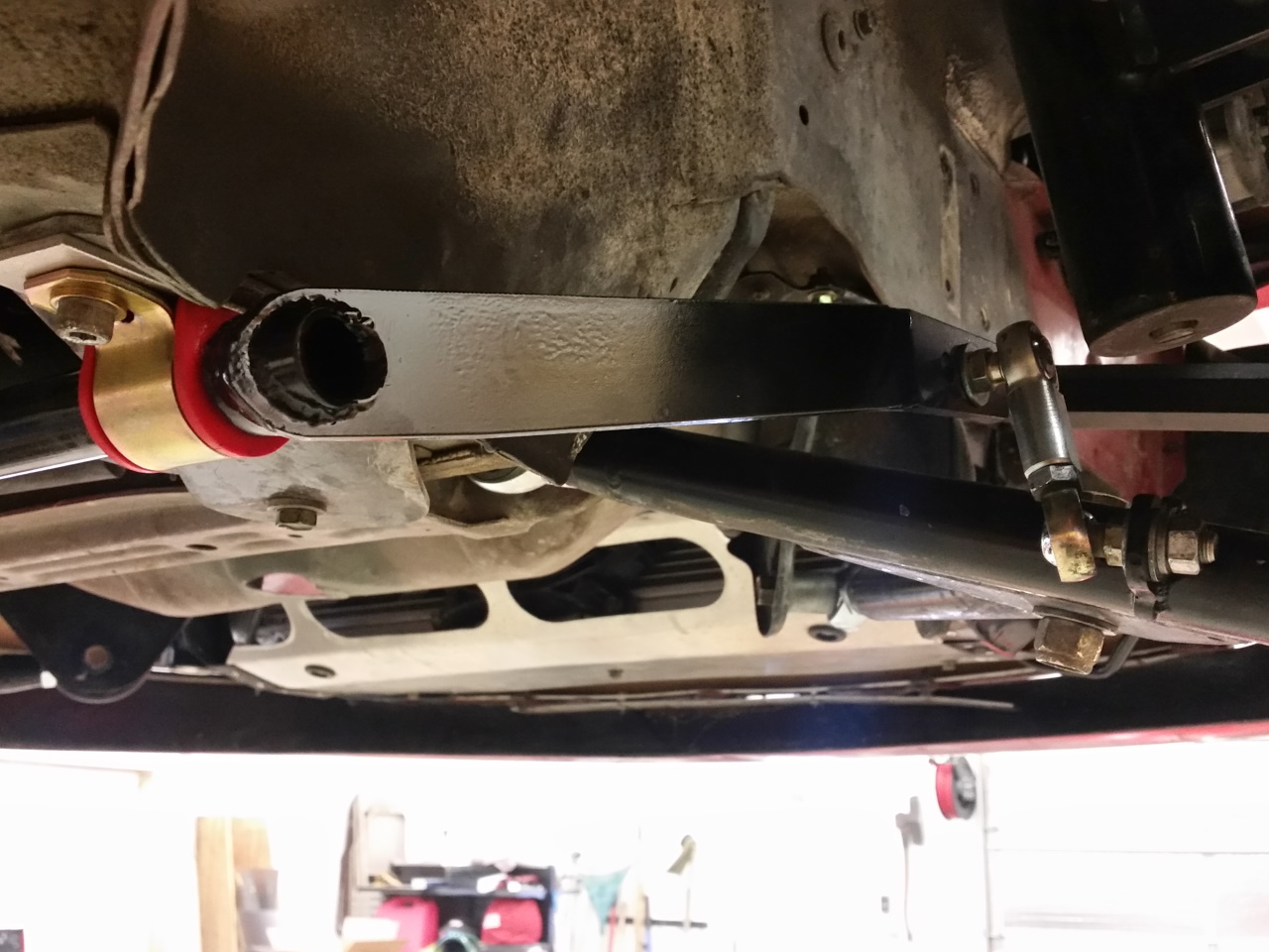 |
With the bar attached to the control arm, the motion ratio is substantially less than it was when attached to the strut. This means the bar needs to be stiffer to have the same effect. My goal was to have slightly more stiffness than I had with the strut mounted Whiteline bar that I was running before, and to achieve this I ended up using 1" OD x 0.109 wall tube for the new sway bar. The calculator I used to figure this out can be downloaded below.
As mentioned above, I built this bar a little over a year ago, so I have had a chance to use it for a while. Overall, I think moving the attachment to the control arm was worth while. It seems to improve steering feel and prevent bumps from feeding forces back into the steering.
Koni Adjuster Knobs
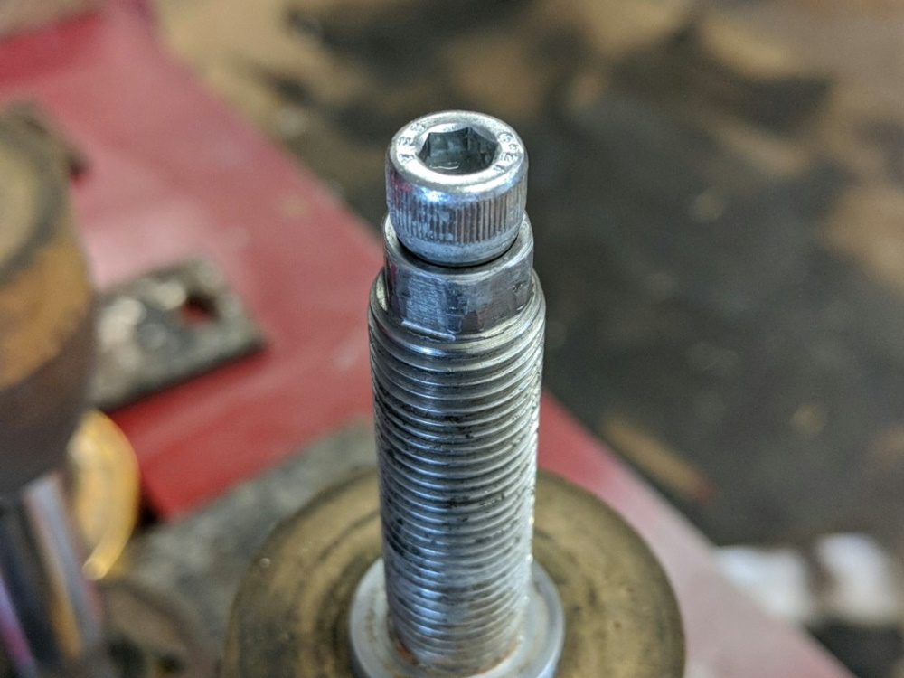
This is one of those little things that just came to me in the midst of another project. I have never liked the adjuster on Koni shocks. It is even more of a pain when you bury the adjuster under the chassis behind a tiny hole as I have done. In the past I have used a modified Koni knob with a piece of stainless steel tube glued into it with the end slightly flattened. This worked, but wasn't great. Finally I had the thought of doing something about it. So I took four M6 socket head cap screws, cut the heads off of them, and bored a 1/4" diameter hole in the bottom of the head using the lathe (sorry, no pictures). The hole ended up about 1/8" deep before breaking through to the socket. I cut the end of the Koni adjuster tab down to about 1/8" as well, and JB Welded the screw head to the Koni adjuster. Some care was required to make sure no JB Weld got where it shouldn't, and to keep the new knob straight as it cured, but overall it wasn't too difficult. Now I can adjust them with a 5mm hex key.
The adjuster they should have had all along! Koni, if you are listening... great shocks, crappy adjuster!
Bump Steer Check
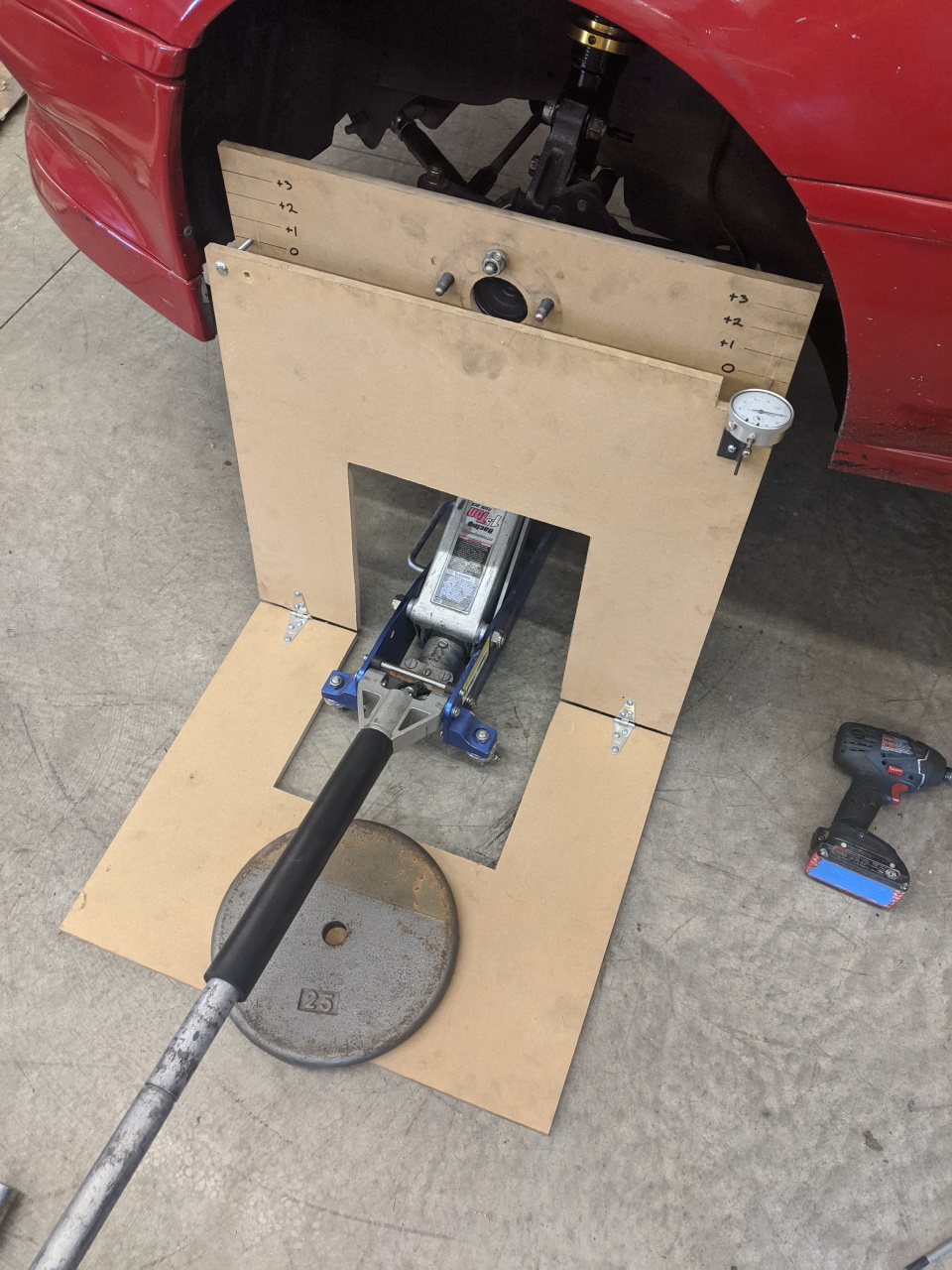
Last thing! With all the geometry changes I made, a double check on the bump steer is necessary. I had of course checked this in my model as well in order to be reasonably sure it wouldn't get too out of hand. But it is hard to measure the chassis and all of the various pieces accurately enough to get a really precise read on bump steer in a model. A check in the real world is always best. Here's my home made bump steer gauge in action. The process is pretty simple. With the spring removed, you jack the suspension through it's range of motion, and read off the toe change on the dial indicator.
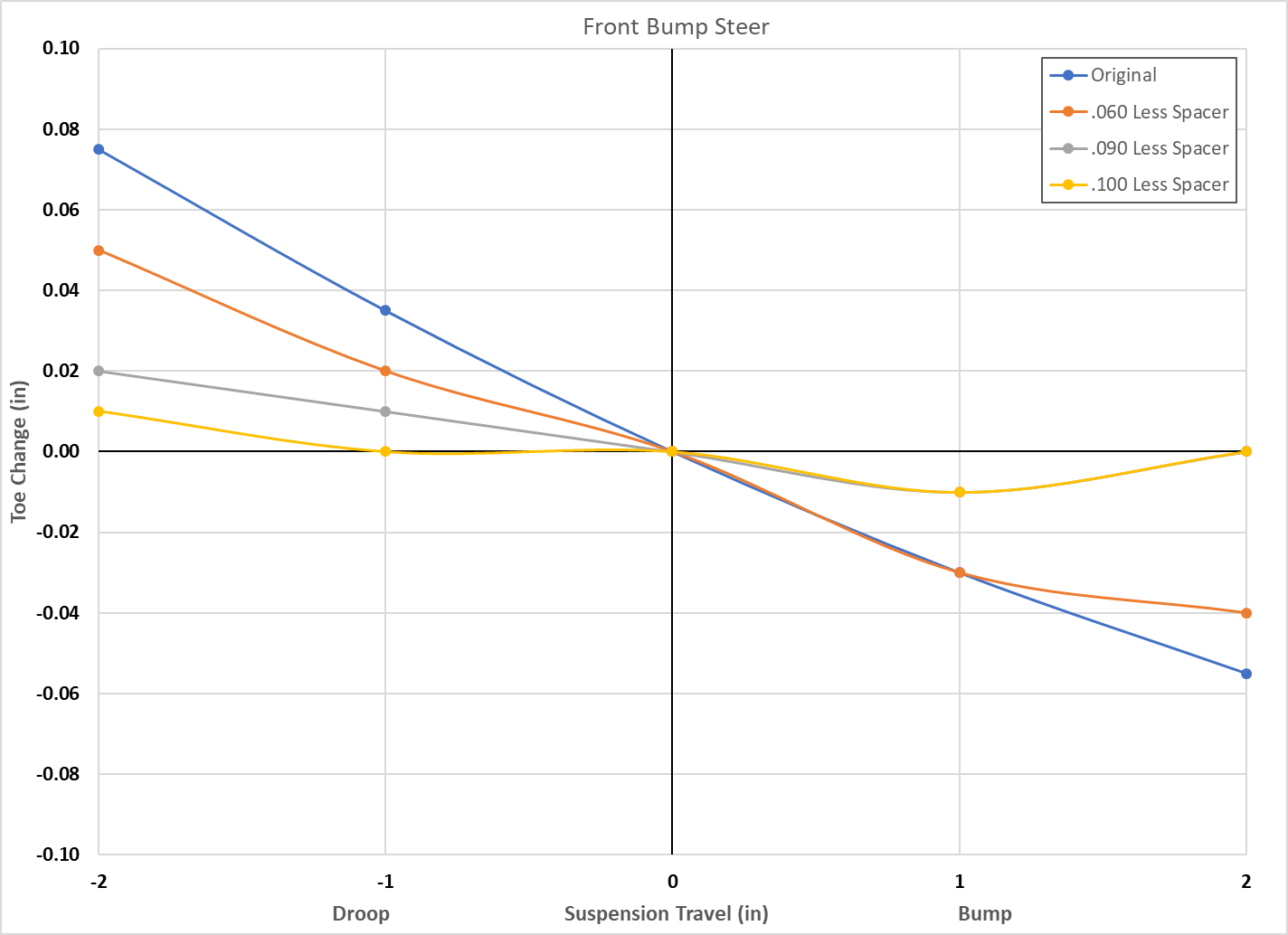
The front initially needed some work, as it was showing quite a bit of toe in on droop and toe out on bump. Removing bump steer spacers from above the outer tie rod end brought it down to pretty nearly zero change. The graph below is plotted from my real world numbers, not from the computer model.
The rear is a bit harder to adjust, but fortunately it didn't really need any adjustment. Slight toe in on bump, slight toe out on rebound.

How much difference will all of this make in the real world? Hard to say, and the way this year is going I may not get a chance to find out any time soon. But it should reduce body roll, and the improved camber curves should help grip. And hopefully getting that front roll center under control improves the overall feel and stability of the car. I know that is one of the primary benefits to my basic geometry kit, and this is a similar (though smaller) effect on the geometry.