
The ABS system in the MKII MR2 is known to be a bit... let's just say it was the best they could do in 1990... Toyota did improve it quite substantially in 93, and I had retrofitted a 93 ABS ECU into my first MR2, but that only helped so much. But what about something more modern? Like the system from the MR2 Spyder?
I'm not the first person to do this, not by a long shot. In fact it was done almost 10 years ago that I know of, and I'm sure it has been done by a few people since. This is just how I did it.
There are two versions of the Spyder system. Both are 4-channel systems, compared to the 3-channel system in the MKII (at least, the 91-95 cars available in the US, 96+ cars in other markets had a 4-channel system). The 2000-2002 system has a separate ECU under the dash, just like the MKII system, while the 2003+ system incorporates the ECU into the ABS actuator for a completely self contained unit. I used the 2003 system in my car. I don't know if it is more advanced in any way than the 2000-2002 system, but it seemed to me worth while to get the newest system I could.
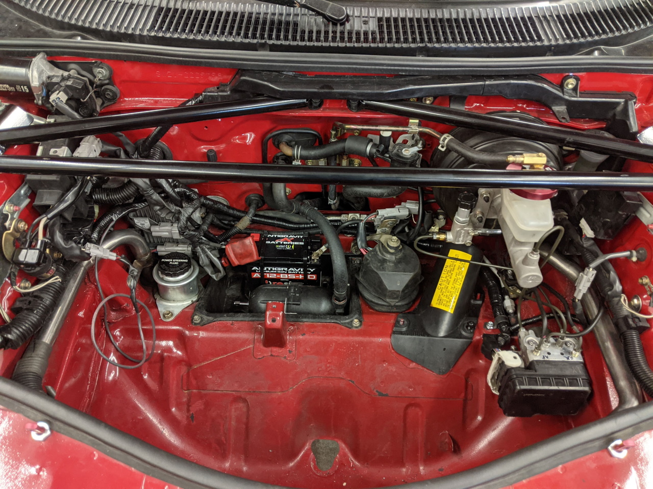
Either of the systems represents a pretty considerable weight savings vs the original system, not to mention being MUCH smaller. Here's the ABS module out of my 91 next to the 2003 module:
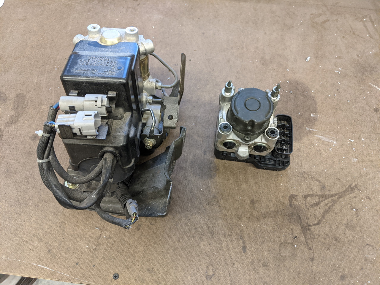
The Spyder ABS module weighs ~4lb. The old module with it's brackets, plus the separate ECU and it's bracket, weight 14.5lb. So all in all it's roughly 10lb saved to go from the 91 system to the 2003 system.
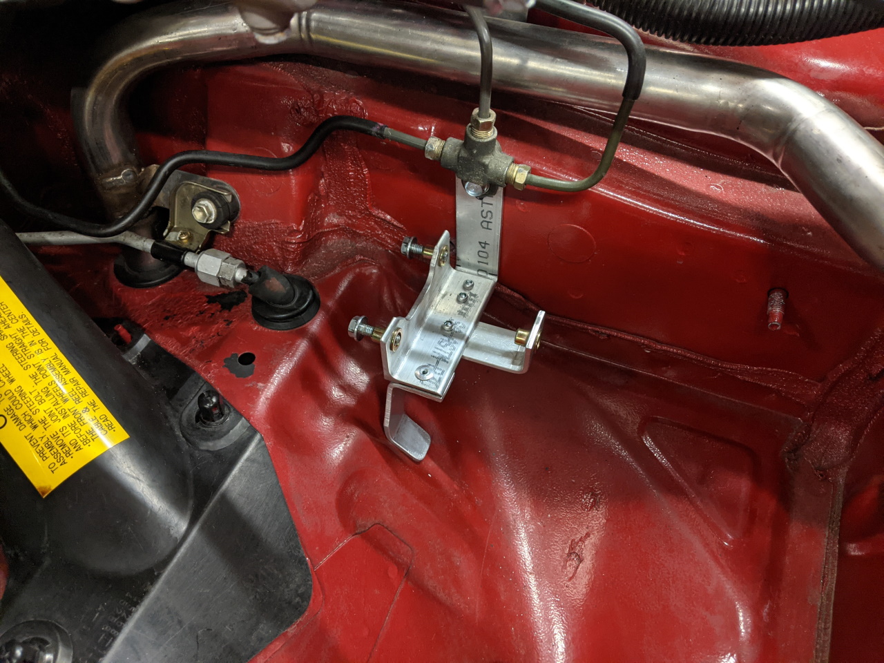
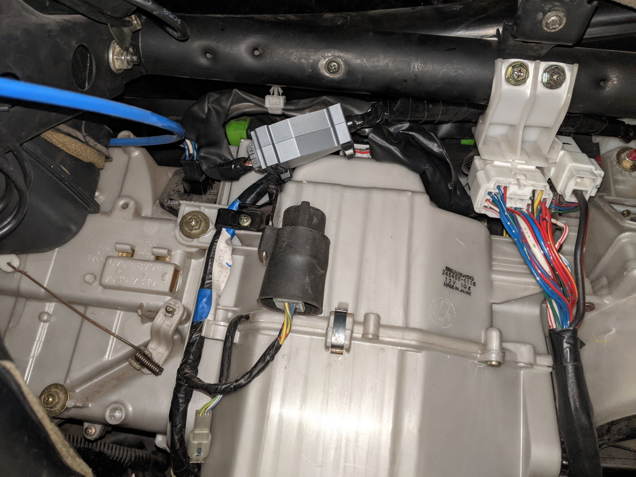
I built a small aluminum bracket for the Spyder module out of some scrap bar stock and a piece of angle. The spyder module mounts via 3 rubber bushings in the bottom of the module. Mine was missing one from the junk yard, so I replaced it with a piece of rubber hose. An M6 rivnut makes a convenient peg to fit into this new bushing (the forward most attachment point). For the two rear attachments I installed two more rivnuts and threaded bolts through them backwards so that they will protrude out into the rubber bushings on the module, locking it in place. The bracket mounts to one existing bolt hole, plus one rivnut that I added in the floor (not yet installed in this picture).
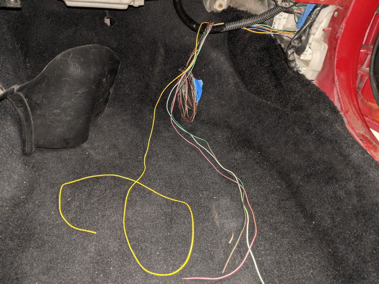
This car didn't come with ABS, although some of the wiring was already in place (for various reasons). For example, the dash harness has all of the ABS wiring and the connector for the ABS ECU. The body harness was actually the Turbo body harness from my first MR2, which I had swapped in when I installed the 3SGTE in this car, and then modified when I swapped to the 2GR. So a connector for the ABS sensor was present for the left rear, but it's in the trunk due to my routing of the harness through the fender instead of the engine bay. I'm not sure if this chassis ever had a connector for the right rear, but it didn't at this point. However I did still have the old cruise control harness (probably from my green car), which also includes the wire for that sensor.

Since cruise control on the 2GR is a single wire from the dash to the ECU instead of all of this, I definitely won't ever need that portion of this harness. So I took it apart and de-pinned the cruise control stuff, leaving me with just the three wires for the ABS sensor. Two for the sensor itself, and one for the shielding. A note on shielded wires! The shielding must be grounded in order to function. This means that any place where the shielded wire goes through a connector there is an extra pin to pass the shielding through the connector to maintain continuity of the shielding back to the ground point. It is very important to maintain this continuity of shielding.
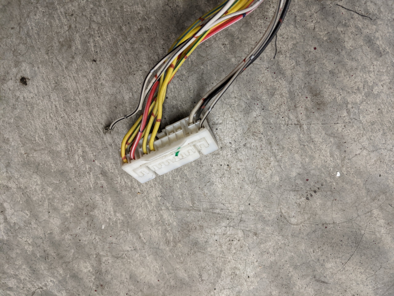
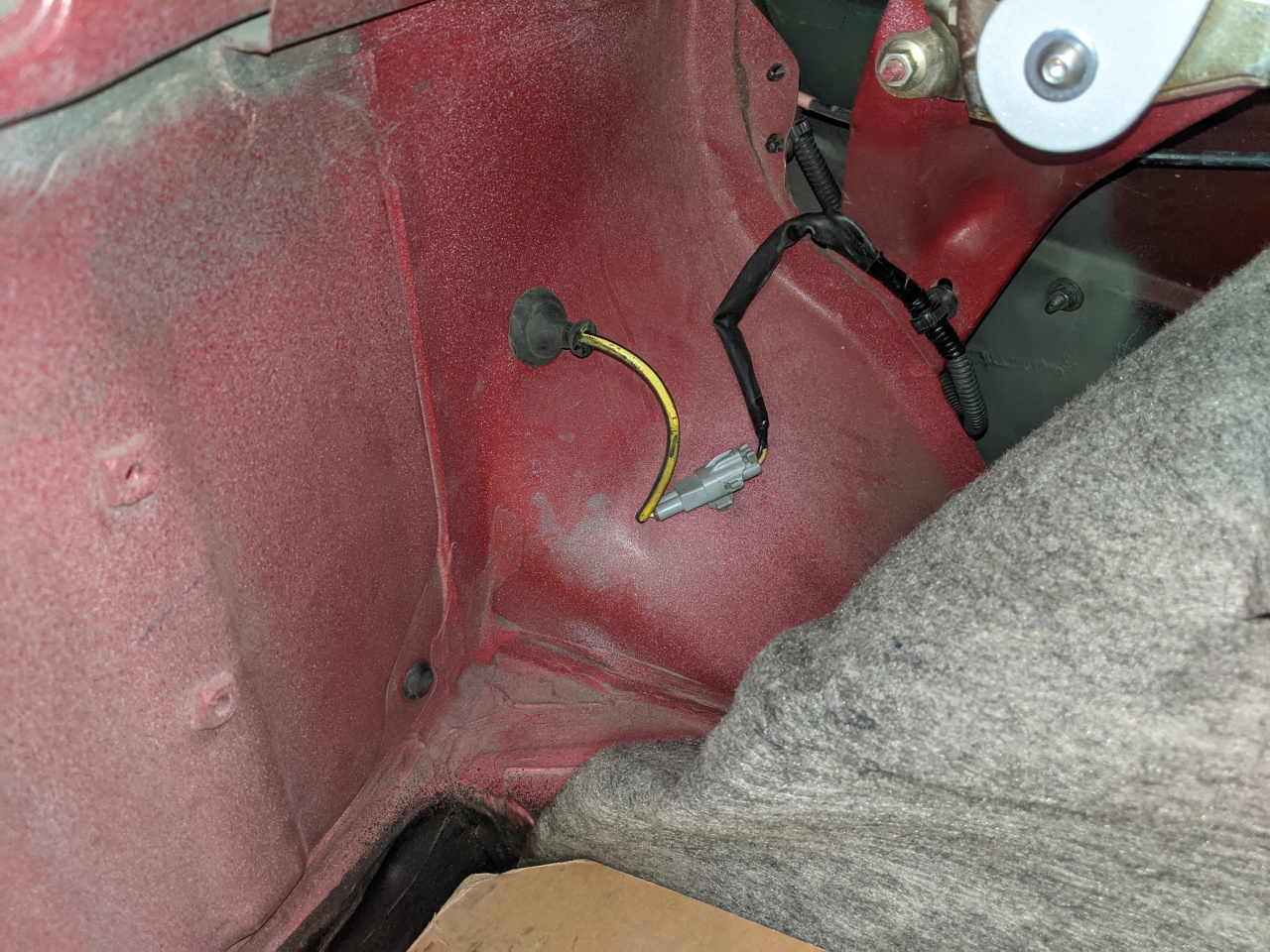
Here's the connector for the RH kick panel where this harness will join to the dash harness (which already has the ABS wiring). With all the excess removed I wrapped the ABS sensor wire up in some sleeving and routed it through the RH fender to mimic the routing of my body harness through the LH fender.
 |
 |
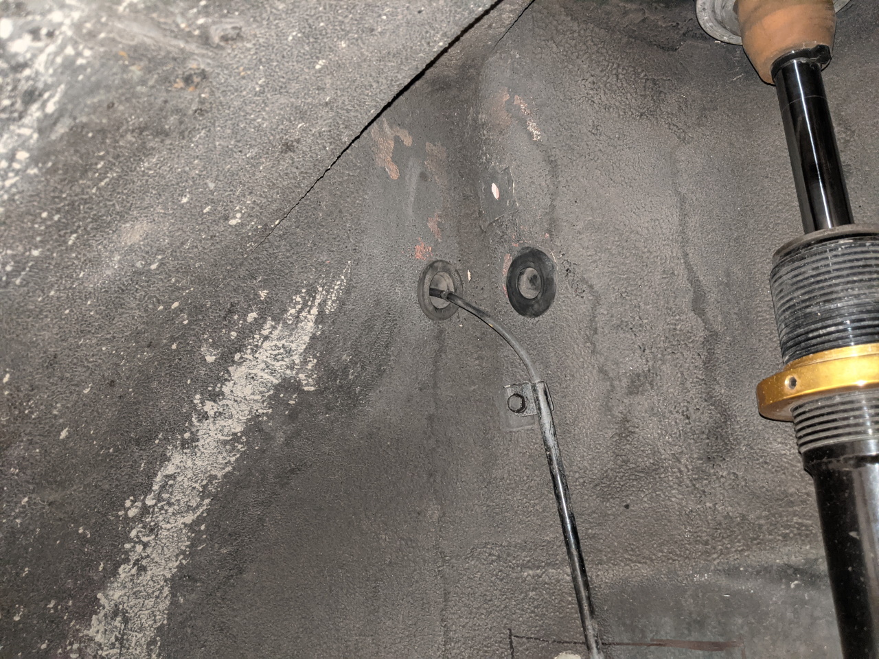
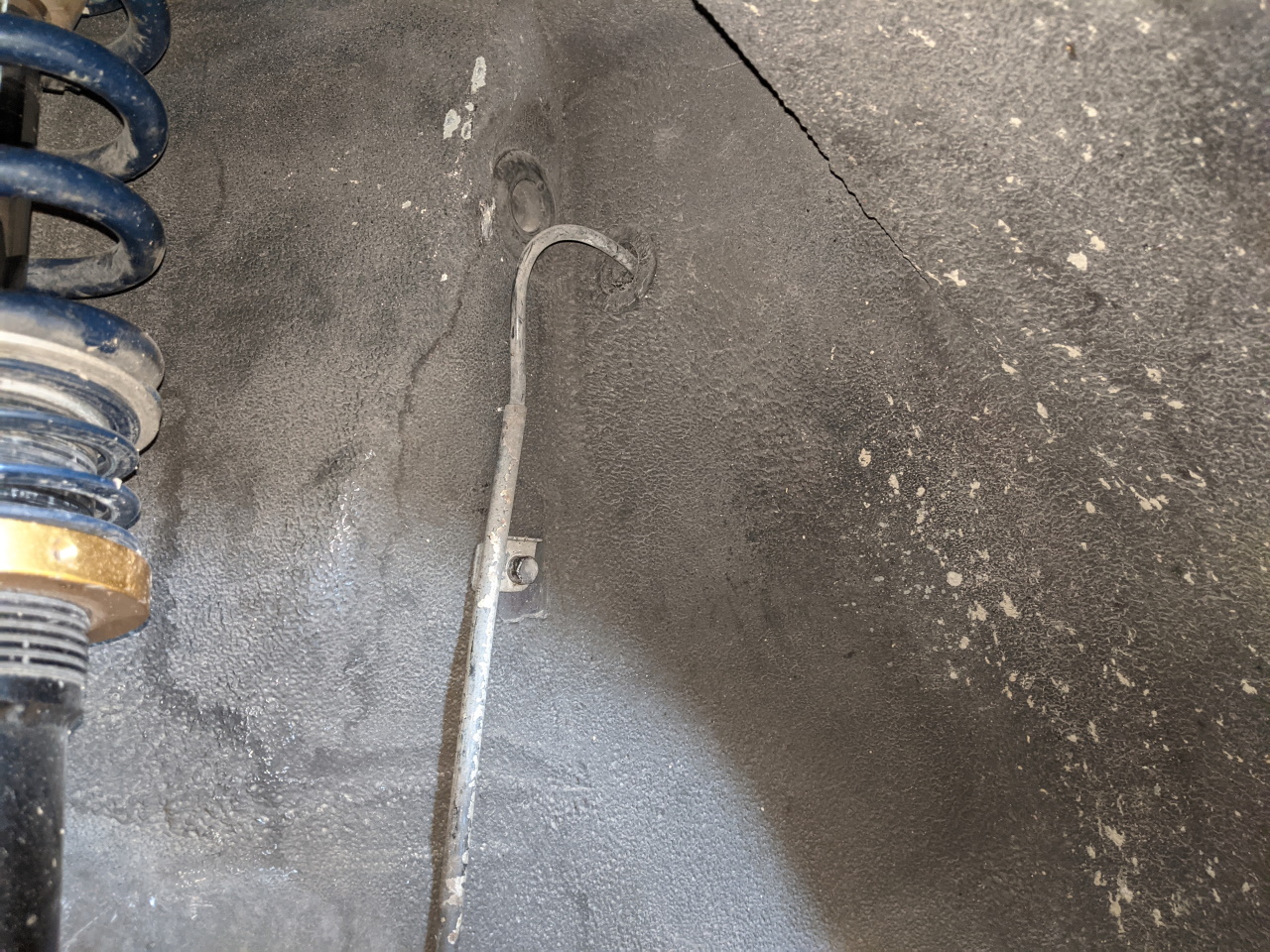
Despite their alternate routing I had just enough length on both this wire and the body harness connector to reach the stock disconnect point for the rear sensors. However I decided to do something a little different and route the sensor wires directly into the trunk rather than through the engine bay. So I drilled new holes from the wheel well to the trunk as shown below. Nice and clean.
 |
 |
 |
 |
Fortunately I had kept all of the ABS sensors from my old car, and had swapped over all of the ABS compatible hubs and knuckles when building this car. Otherwise this conversion would have been a lot more work and a lot more expensive!
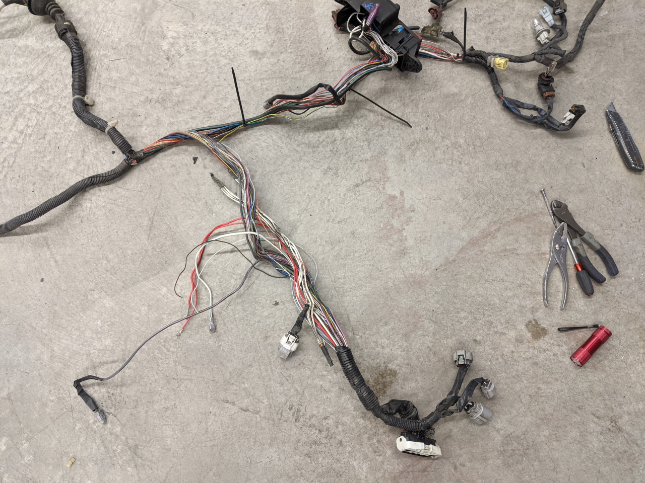
I bought a complete Spyder frunk (or "luggage room" as Toyota calls it) wiring harness in order to get the connector and the wiring associated with the ABS system. Not the cheapest way to do it, but it saved a lot of splicing vs buying just a pigtail, and this way nearly all of the wire colors match the factory Spyder wiring diagram all the way to where they interface with the MKII wiring. Here's the Spyder harness, the ABS module connector is the big one in the bottom center of the picture.
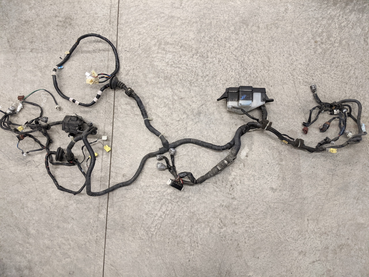
The three smaller connectors next to it are for the Spyder power steering system. I almost swapped that in as well during this project. Much like the ABS system, it's a self contained unit with the pump, reservoir, and all electronics in one. It's much simpler than the MKII system and should be a bit lighter weight. Maybe it's better as well? I know the 91 MR2 power steering system has trouble dealing with quick transitions, although this was improved in later years, and the ECU can be swapped in to get those benefits (I have done this on my car). I the end I will stick with my original power steering system for now, although I will certainly keep the wiring for the Spyder system... just in case ;)
Getting the power steering wiring out of the Spyder harness involves a pretty thorough dissection. Portions of it run nearly from one end of the harness to the other.
 |
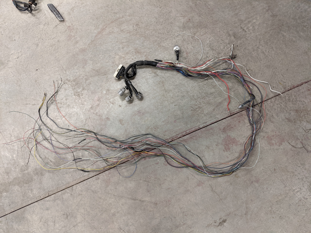 |
At this point that is the ABS and power steering wiring. Later the power steering stuff will get separated out.
Next I test fit the harness. There is plenty of length on everything except the two main power wires, which will have to be extended to reach the fuse box. The LH sensor connector is a different type of connector than the MKII and will need to be swapped. The RH sensor plugs right in, but the wire is excessively long and so I may end up shortening it later.
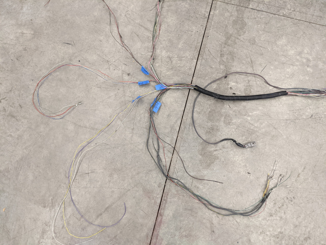
With the test fit complete and the length needed to reach the connector on the dash harness I spent some time with the wiring diagram labeling the wires. A few notes on that:
-The Spyder ABS system includes four speed outputs, one for each wheel, which normally would go to the transmission computer. I don't have a use for them at the moment, but I will keep them just in case. Maybe traction control some day? Maybe data log them just for fun? Who knows.
-The Spyder system ALSO has a single speed wire. I initially assumed this was a speed input (something the stock MKII system doesn't have). Later I learned that the Spyder doesn't have a speed sensor in the transmission and instead uses the wheel speed sensors to determine vehicle speed. So this is in fact a speed output. I have been wanting to convert my car to an electronic speedometer, but the speed sensors for the E153 transmission are somewhat rare and expensive... In theory I should be able to use this speed output to drive the speedo as provide a speed signal to the engine and power steering ECUs. But that's a project for another time. (Not long after finishing the ABS install I did finish the speedometer conversion as well, read about it here.)
-There are three wires that would normally go to the OBDII port. However they are use din the same way as the diagnostic system on the MKII, shorting pins and counting flashes. My car doesn't have the diagnostic port in the engine bay any more, so I will just leave these behind the glove box, labeled and with some spade connectors on them, just in case.
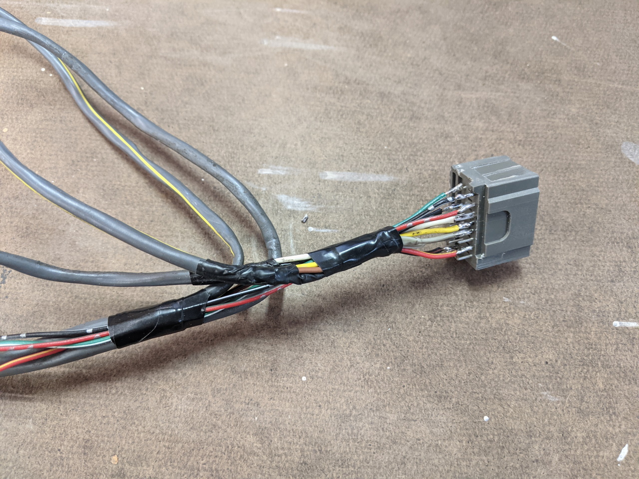
-Other than power and the front speed sensor inputs, all of the remaining wires connect to the small half of the ABS ECU connector under the dash.
All the other wires go to the 15 pin connector under the dash. I happened to have a connector that matched the connector in the 91 ABS ECU that I had gotten from Tyco Electronics years ago when I was messing with putting the 93 ECU into my 91. You could also salvage the connector out of the old ECU. Since I only needed the small portion I cut it in half, and soldered the wires to it. I 3D printed a back shell to protect the solder joints from being stressed or from shorting on anything.
 |
 |
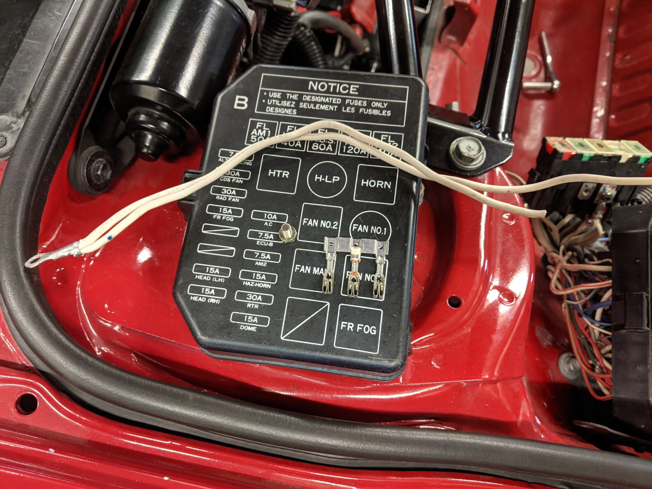
The remaining bit of wiring is to supply power. The Stock MKII wiring provides power to both the ABS system and the power steering system through the 80 amp ABS fuse. The Spyder system uses two fuses, a 30 amp and a 50 amp. While it would have been easier and perfectly consistent with the original MKII wiring to simply tie into the 80 amp fuse, I chose to mimic the Spyder wiring. If I hadn't had another MKII frunk harness that had already been cannibalized I probably wouldn't have bothered, but as it is I was able to salvage a 3-pin fuse box connector that inserted nicely into the two empty slots in the fuse box, plus the fog light fuse which was empty on this car since it wasn't wired for fog lights. I wired this back to the main power input to the fuse box with two wires also salvaged from the other other harness.
 |
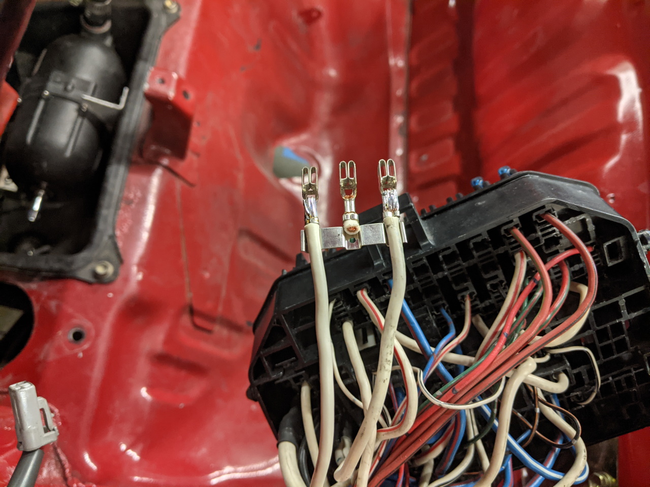 |
Two of the three new fuse locations will be used for the ABS system, the third will remain empty as a spare for future use. You never know.
As mentioned previously the the power wires needed to be extended, and the left front sensor needed a different connector spliced on. Crimp connectors with integrated heat shrink are my preferred way to accomplish this sort of thing. The power wires were also salvaged from my spare MKII harness. They already have terminals on the other end compatible with the fuse box, so they just snapped into place. But if I hadn't had those I would have just put a ring terminal on them and attached it to the 80 amp ABS fuse just like the stock MKII wiring.
 |
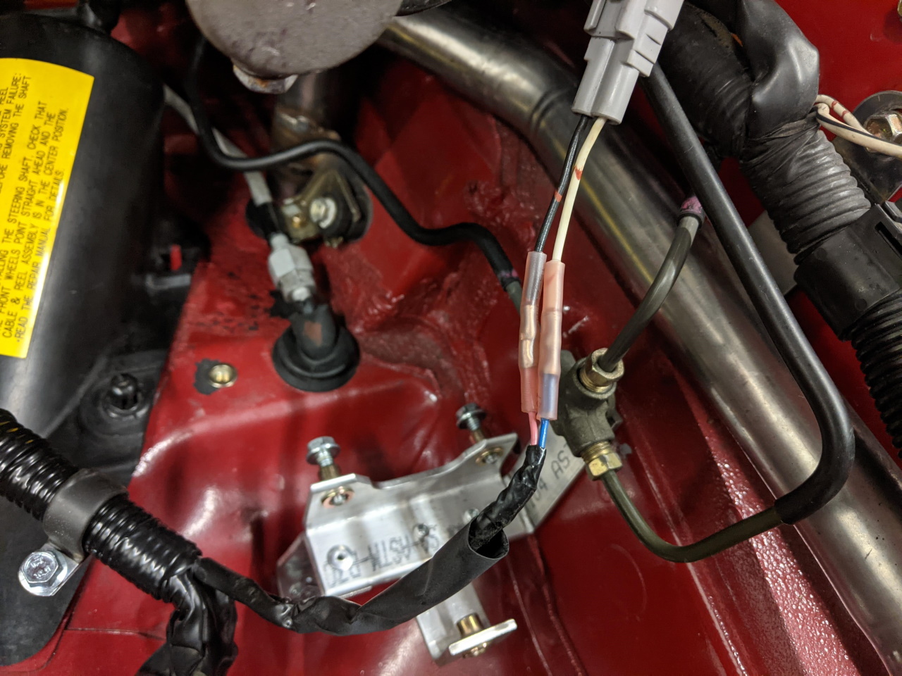 |
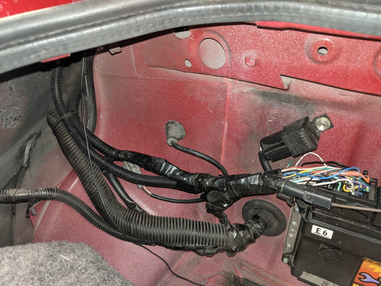
And that's basically it for the wiring. I wrapped it all up with sleeving and electrical tape and routed the main connector into the cabin through a slit cut in the main grommet. This is tricky to do with the A/C evaporator housing in place, but possible. Since removing the evaporator involves venting the A/C system, I struggled through with the evaporator in place. Here's the previously mentioned "extra" wires (speed signals, diagnostic wires), and the 15 pin connector plugged into the stock dash harness. If I ever finish the speedometer conversion the yellow wire will splice into the purple wire (speed signal to the power steering system) at the kick panel. For now, I will just tie them all up out of the way.
 |
 |
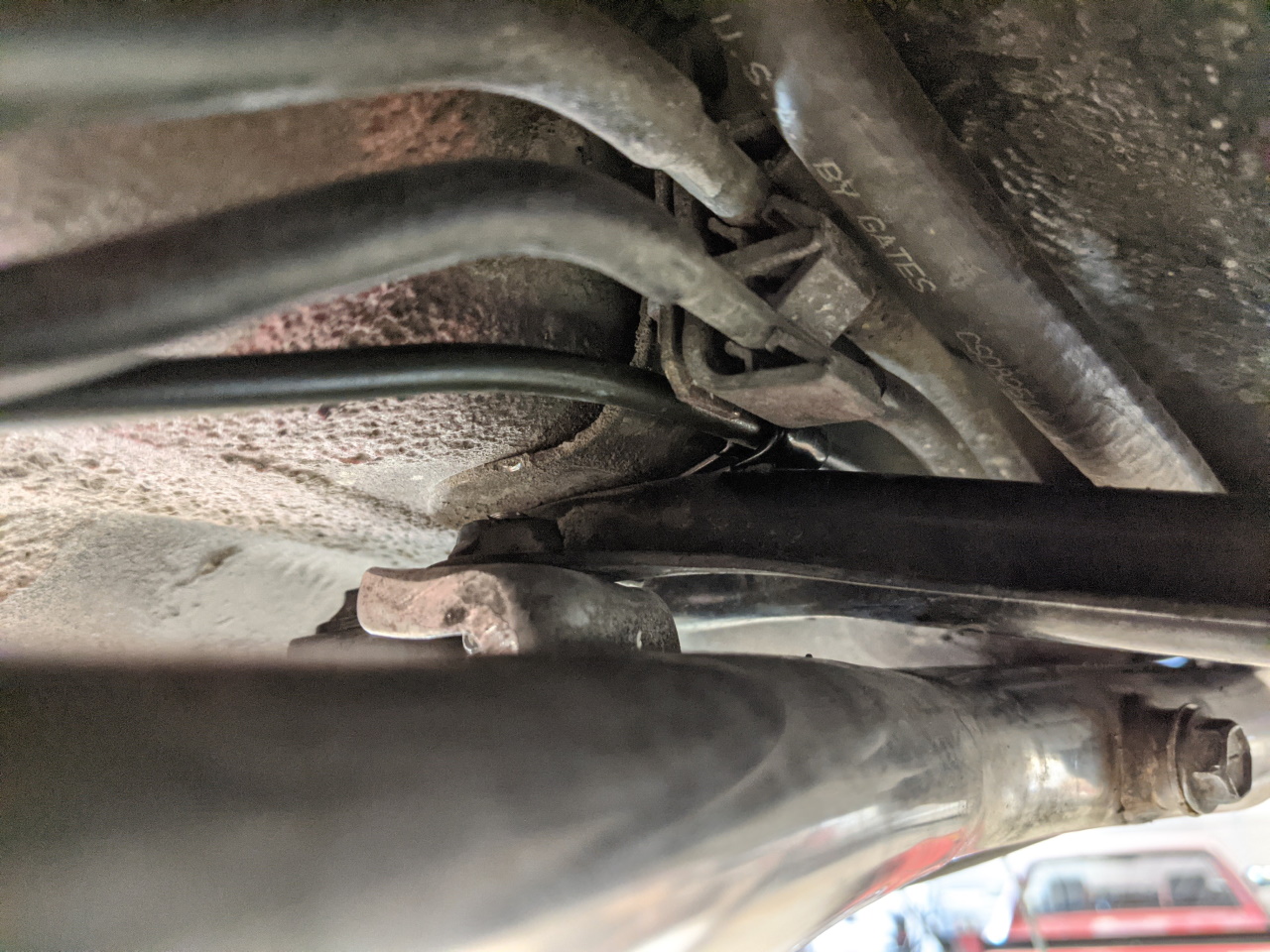
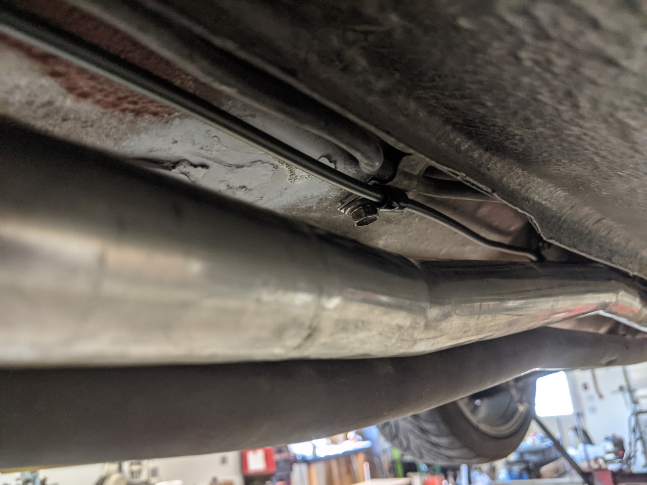
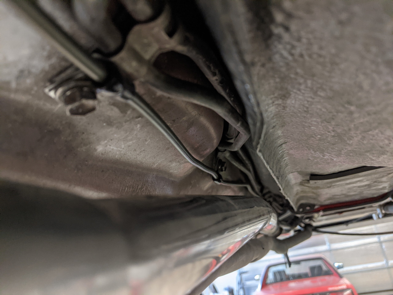
Electrical is done, on to plumbing. As mentioned previously the Spyder system is 4-channel, while the MKII is plumbed for only 3 (rear brakes tied together), so an extra line is needed to the rear brakes. Beginning at the back, I followed the the existing brake line mounting it with p-clamps where I could and in a couple of places with zip ties where I couldn't. This would have been MUCH easier with the fuel tank removed, and I may re-do it if I ever drop the tank for another purpose, but at this point I didn't feel like dropping the tank just for this.
 |
 |
 |
 |
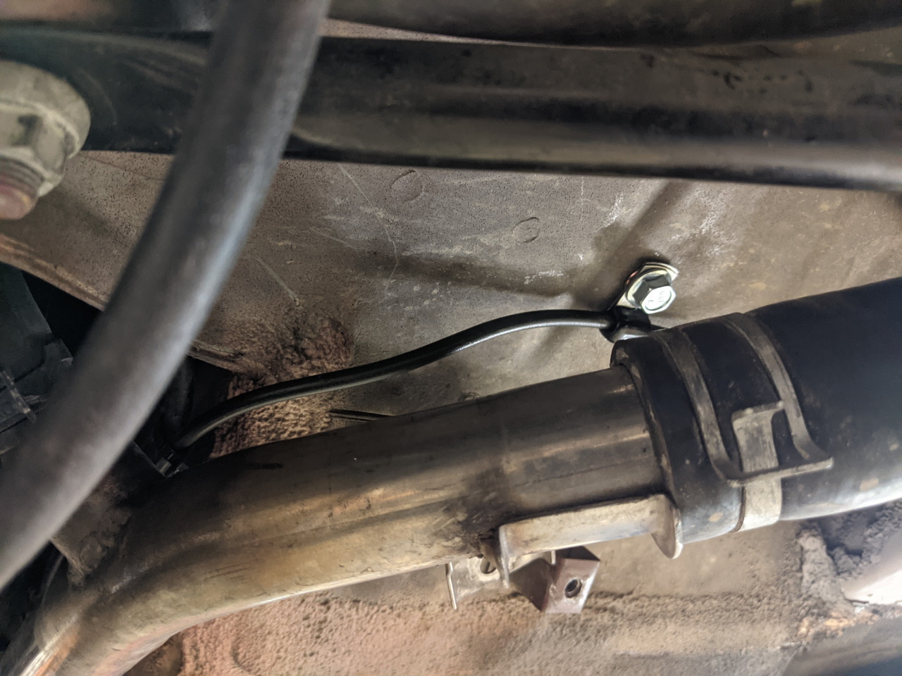
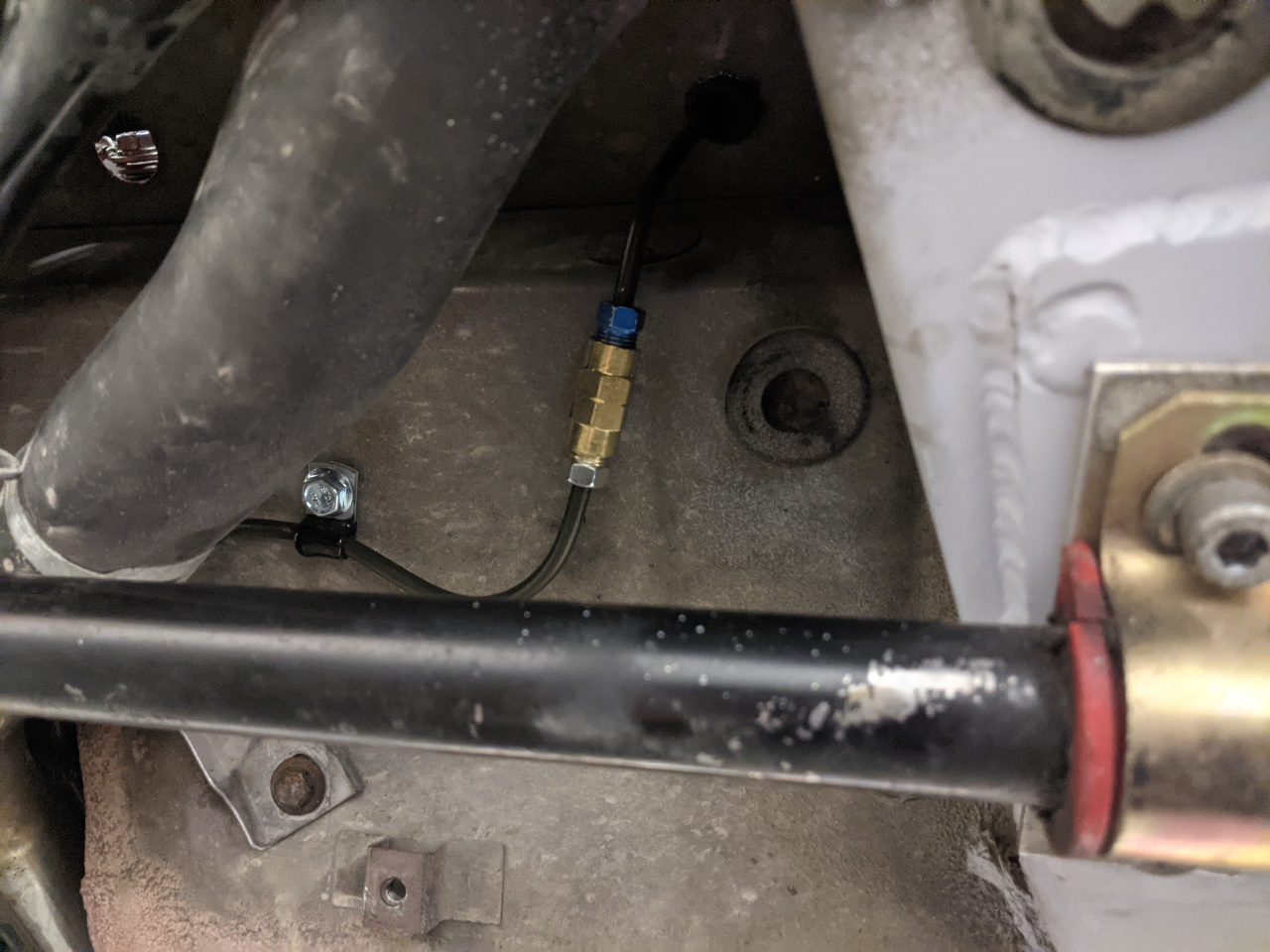
At the front, rather than following the stock line up past the front of the tank I turned left and followed the coolant pipe. I added a rivnut here for a p-clamp, and will drill a hole to pass the line up into the frunk near the coolant pipes pass through.
At the module, I was able to make stock brake lines work for three of the four connections. All had to have their bends adjusted, but there was enough length to do so. The stock non-ABS left front line is too short, but the ABS version works nicely. The stock non-ABS right front worked, although the ABS version is a little bit longer and may have worked slightly better. The stock ABS line for the rear brakes also works.
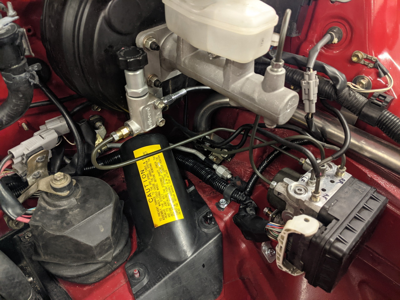
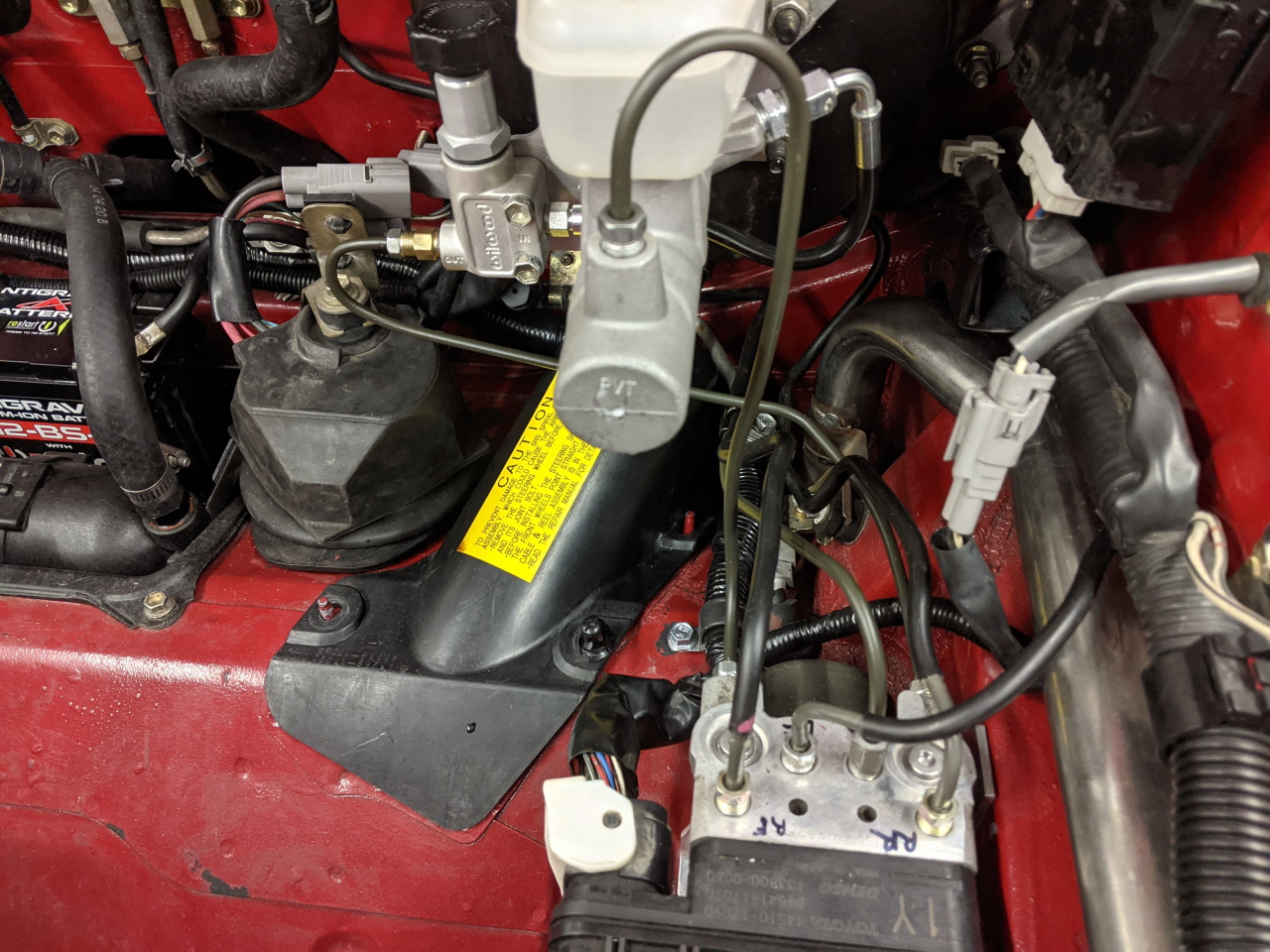
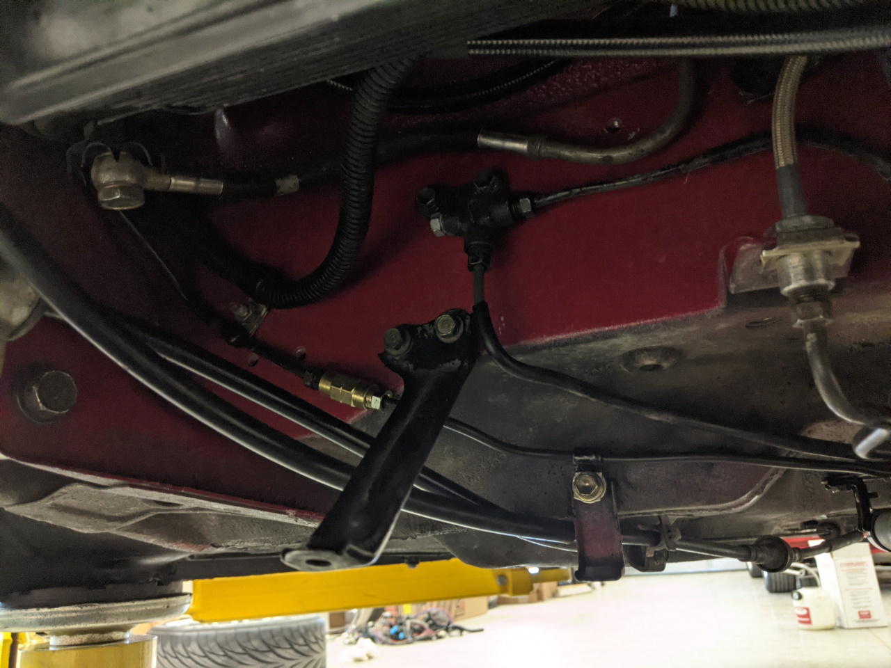
I made new hard lines from the master cylinder and proportioning valve to the ABS module. The line from the master cylinder to the proportioning valve is the flex line from my proportioning valve install kit. I added a rivnut and p-clamp to hold the wiring harness a few inches from the ABS module.
Regarding the proportioning valve! The Spyder does not use one. I have read some speculation that there is proportioning built into the ABS module, so after getting everything hooked up I installed pressure gauges on both front and rear calipers to check for any proportioning effect. Up to the 1000 psi limit of my gauges, front and rear pressure followed a direct 1:1 relationship. This was done with the system powered, to rule out any active proportioning that could be done using the solenoids. This leads me to conclude that the Spyder system simply allows the rear brakes to begin to lock up and then the ABS steps in to prevent them locking. Personally I would rather not rely on the ABS to quite this degree, so I will be keeping the proportioning valve in the system, although I will likely set it to a slightly more rear biased setting than I would have without the ABS.
Another angle of the plumbing to the module. I used three p-clamps in a butterfly arrangement to tie all of the brake lines together about half way between the ABS module and the firewall, just to prevent vibration. The new line to the rear goes through a grommet in the floor next to the coolant pipe. The port configuration on the module was determined by examining Toyota parts diagrams and parts catalogs. I am about 99% sure I have them all correct.
At the back of the car, the left rear brake line was bent down and p-clamped to an existing stud in the firewall. The new brake line attaches with a p-clamp and an aluminum space to an existing thread for one of the under cover brackets, and the two are connected with a union. The right rear lines passes through the stock T, with the left outlet plugged. If you wanted to hunt it down, the 96+ MKII with ABS has special union here with two elbows mounted on a bracket that would probably work well. But finding one might be tricky.
At the front, I added another union as well. One note, all of these new brake lines required SAE double flares at both ends. Personally I had a heck of a time creating these, the first step being the hard part. No matter what I did the tube would slip in the flaring tool. I found it suggested online that annealing the tube with a torch before flaring would help, and in my case it helped a LOT. Just get the first 1/4" of tube red hot with a torch and let it cool before flaring.
And that's it! Bleed the system, tighten the connections that you forgot to tighten, and it's done! And if you don't have one, get one of these Motive Power Bleeders. Worth every penny! Also, for a big job like this it's handy to use it to push all of the brake fluid OUT of the system so that you can disconnect lines without making a mess. Just pressurize the system with air only and bleed the calipers until only air comes out. Basically the reverse of a normal brake bleed.

And here's the overall view of the finished install. Well, finished except for shortening that wire to the right front sensor that I mentioned. And it worked, first time. I conveniently had about an inch of fresh snow in the driveway to test it on and it behaved just like it should.
OK, not so fast. There is ONE little problem still... The ABS light in the dash is on. That's odd better check for codes... There is one, code 41, which according to the manual is for low voltage. But the voltage is normal, and the system works... Then I realize that when you turn the key on, the light is OFF for about 3 seconds, then turns ON. Exactly opposite of what it should do. Also when checking codes, it's ON in between codes, rather than off like it should be. Turns out, the output from the Spyder ABS ECU is backwards from the 91. The 91 ECU grounds the light circuit when there is an error, turning the light on. The Spyder ECU applies power to the light when there is an error, expecting the other end of the light circuit to be grounded. The end result is, the light is ON when there isn't a problem, and will presumably turn off when there is. So, a little re-wiring will be required on the back of the gauge cluster to correct THAT behavior.
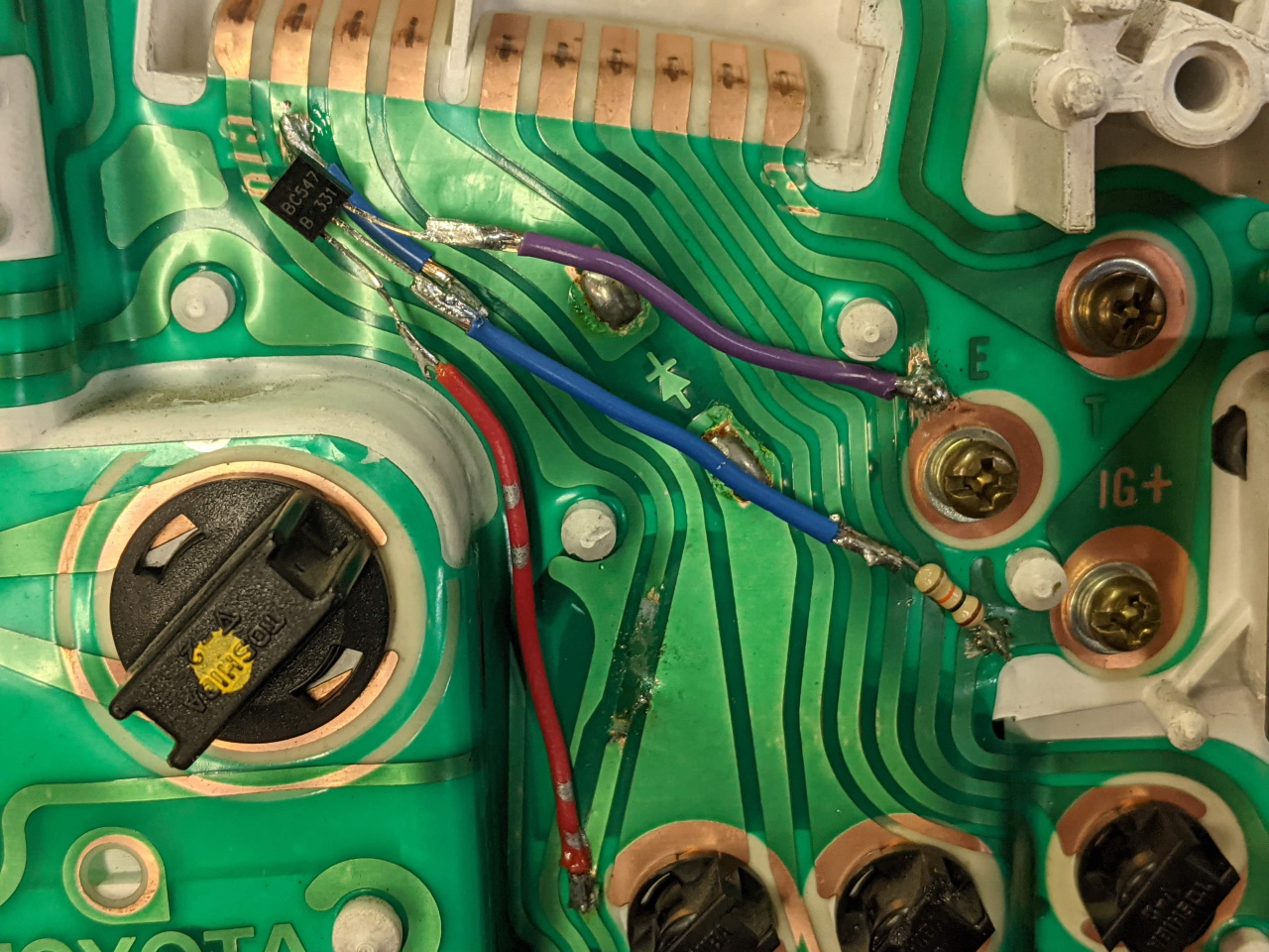
Thanks to Jim King on the MR2OC forum for providing the solution to this. An NPN transistor (BC547 is the part number I bought), a 10k ohm resistor, and some soldering skills are required. I installed it on the back of the gauge cluster as shown below, but it could also be built into the wiring harness somewhere.
 |
|
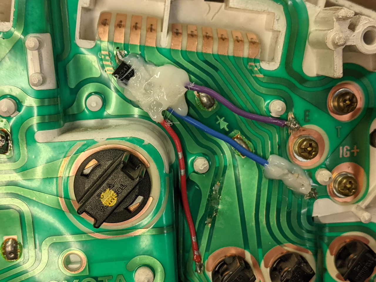
The trace between the input to the cluster and the bulb is cut (next to the red wire), and the "base" (middle pin) of the transistor is connected to the input, and also to a 12v power source via the 10k ohm resistor. The transistor "collector" (left pin when viewed from the flat side) is connected to the bulb via the blue wire, and the "emitter" is connected to ground via the purple wire. Soldering to the plastic circuit board is a little tricky, but not impossible. Just need to be careful not to apply to much heat. I finished by encasing the exposed leads in hot glue to insulate and protect it all, as well as securing the transistor to the back of the cluster.
Resources:
Wiring diagrams for the MKII (91 and 93+ versions) can be found here.
Wiring diagrams for the '03+ Spyder ABS and also the '00-'02 system.
'03+ Spyder ABS diagnostic system.
'03+ Spyder ABS diagnostic codes.
'03+ Spyder ECU pinout diagram.