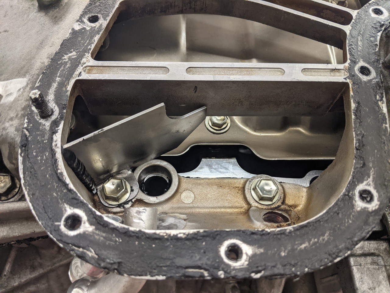
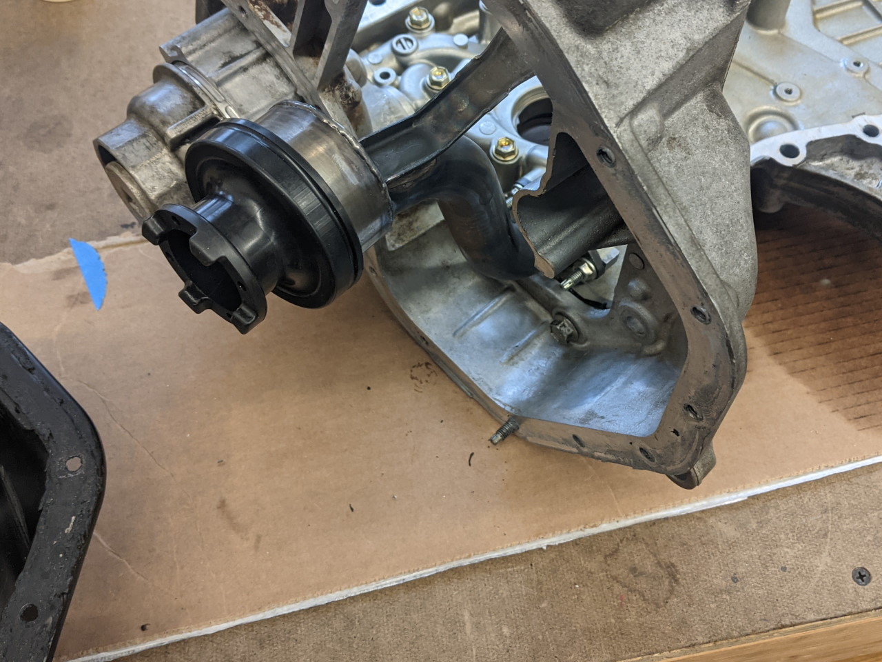
While I had my 2GR torn apart to fix and upgrade it, I took the opportunity to attempt some improvement on the oil drains from the cylinder heads.
As I have mentioned before, the 2GR suffers from some oil starvation in RH corners. If you watch this video (keep an eye on the left hand gauge at the bottom of the screen) you can see the oil pressure drop at about the 54 second mark. There are a couple of causes of this. One is that the oil pickup is towards the RH side of the motor, so on a RH turn oil tends to flow away from it. Some oil also tends to get "stuck" in the heads, due to the location of the drain tubes from the heads back to the pan. And even the oil that does drain back to the pan, a large portion of it drains back to the upper portion of the oil pan at the LH end of the motor where it doesn't do any good. A good bit of technical discussion on the Frankenstein Motorworks Discord Server precipitated the following improvements.
Part of the problem is the position of the drains in the head. Each bank has three drain tubes. However they are not evenly distributed. On the front bank (bank 2) the last drain on the left end is 3-4 inches from the end of the motor, as shown below. This means that on RH turns, there is a pretty large volume of oil that can get "stuck" in this area and not drain until the turn finishes. Since the PCV valve is right above this end of the head, it also means that the PCV tends to suck oil on RH turns.
Similarly, on the rear bank (bank 1), the first drain on the right side (timing chain side) is 3-4" from the end. And while LH turns are not the primary problem, I figured maybe I could improve on this as well.
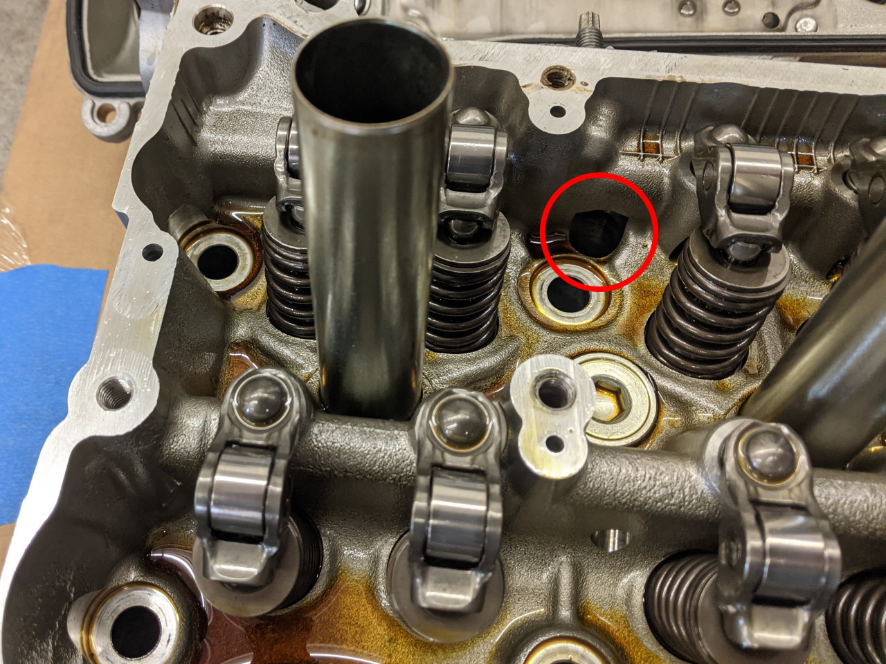
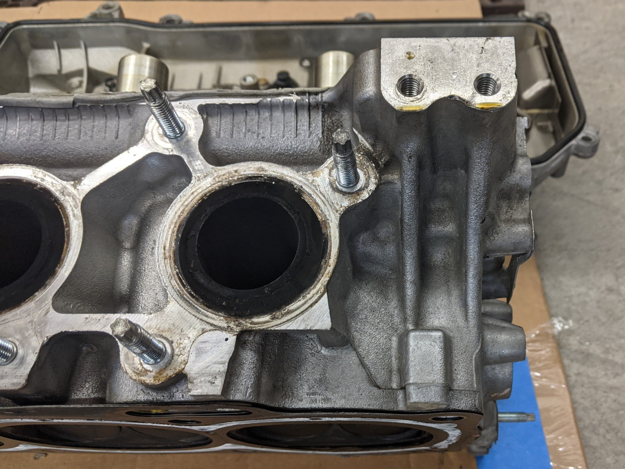
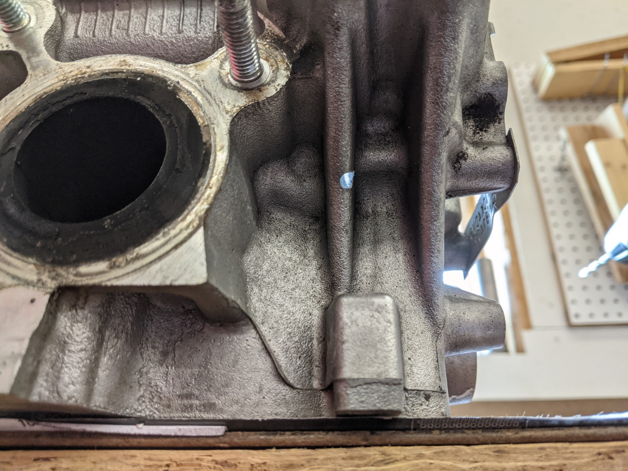
The only way I could see to improve the forward head was with an external drain. This would have to exit through these ribs on the outside of the head. Tricky, but do-able.
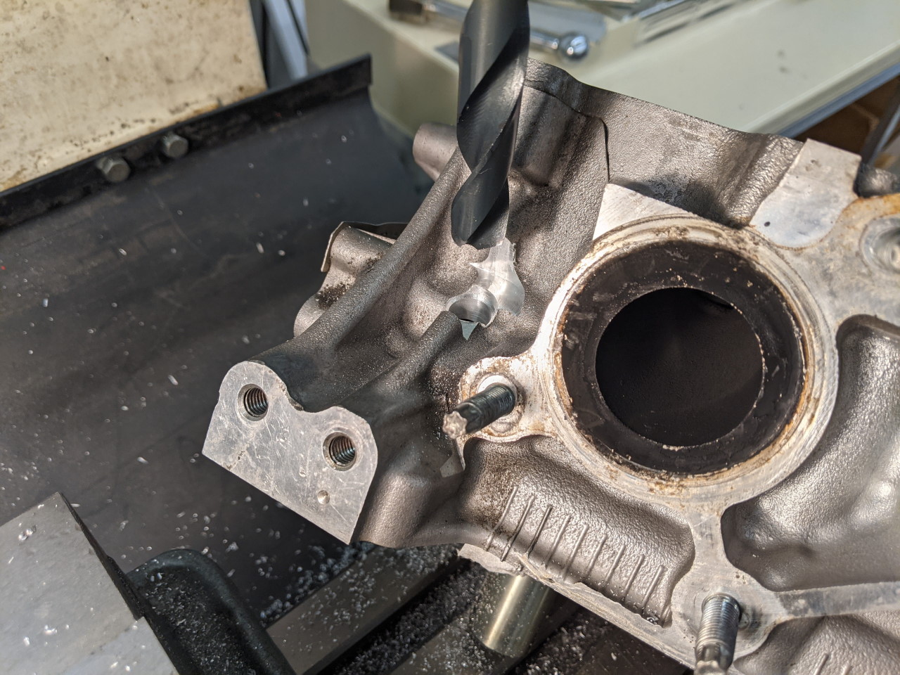
This drain started as a pilot hole drilled from the inside.
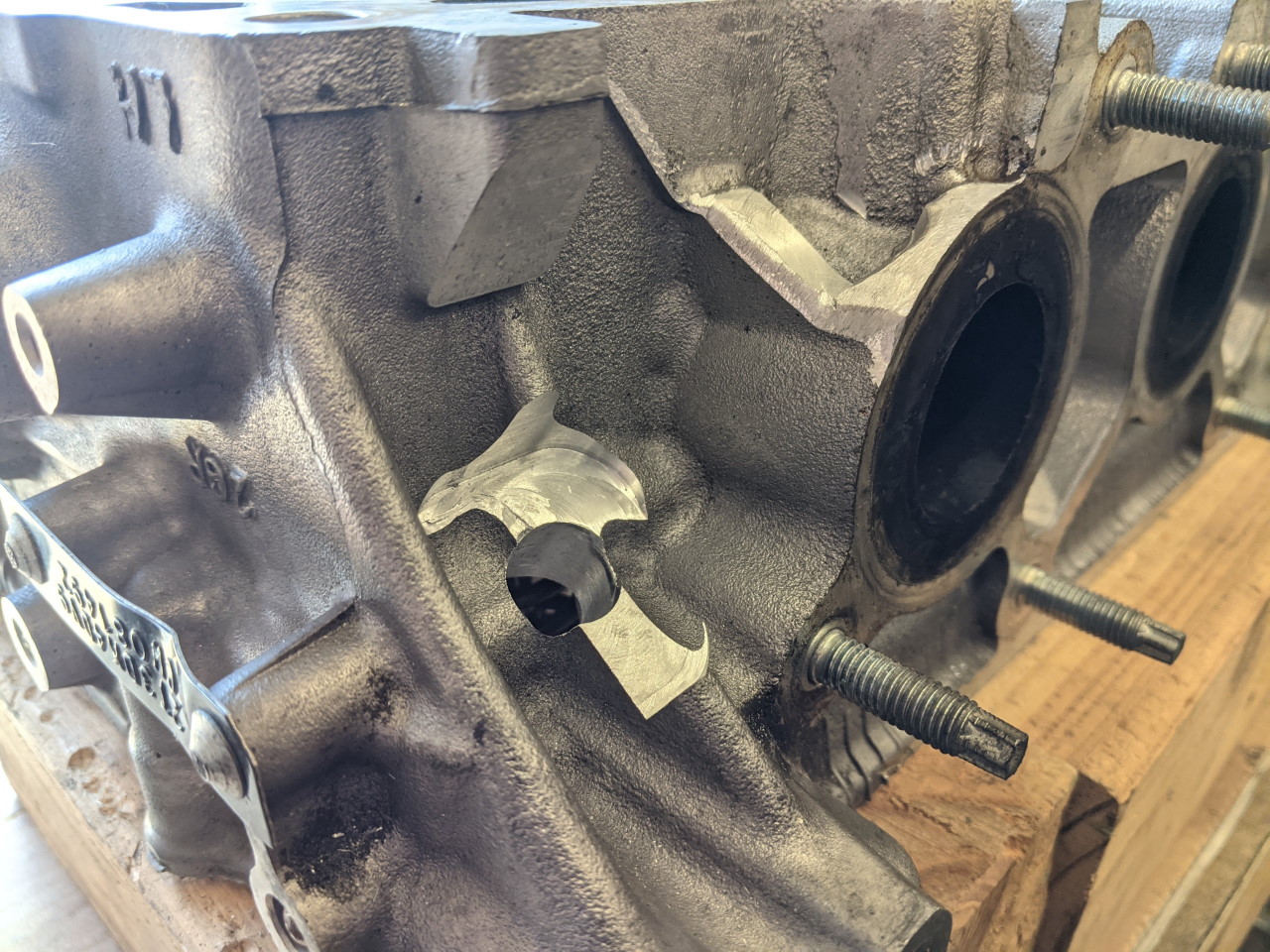
I then moved the head to the mill and set it up with some wood blocks so that it sat at the proper angle to drill the hole out to final size (3/8 NPT was the goal), as well as machine off some of the rib and surrounding extra material to make a flat spot and make room to install the 3/8 NPT to 8AN fitting.
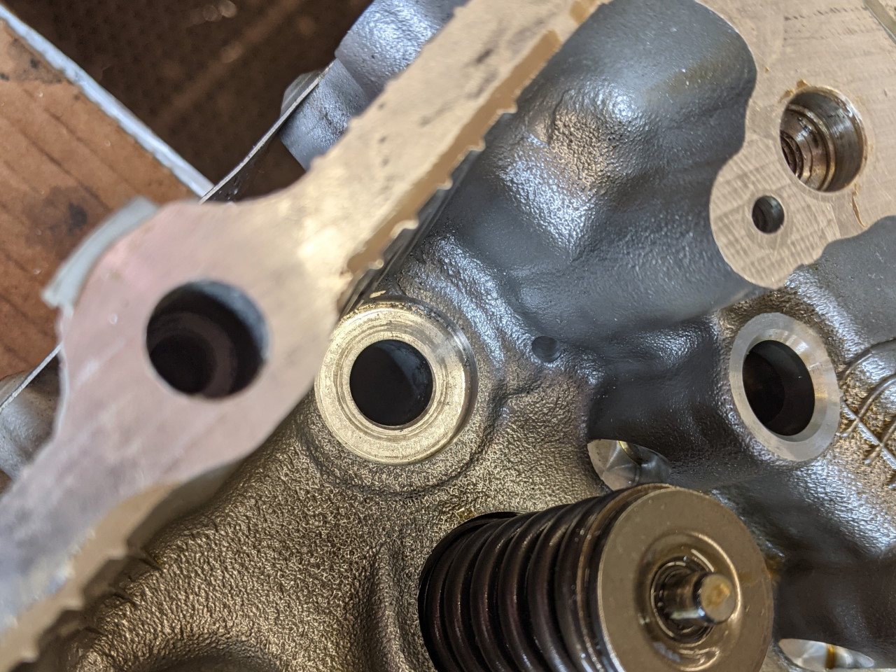
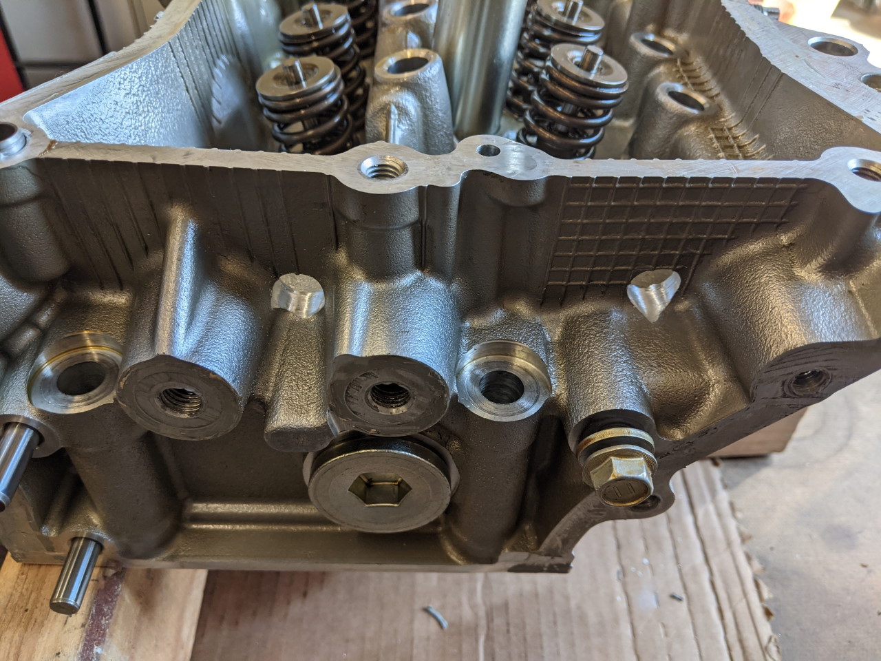
At the other end of the heads, it's a little easier. I simply drilled two 9/16" holes in each head through the end to allow oil to drain through the timing chain area. LH turns aren't a big problem, but this was a really easy way to improve the drainage in that direction. I figured it couldn't hurt. Rear bank on left, front bank on the right:
And here's a top down view of the new holes in the rear bank.
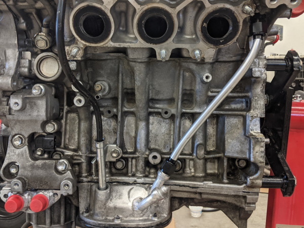
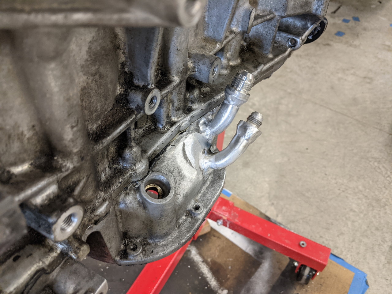
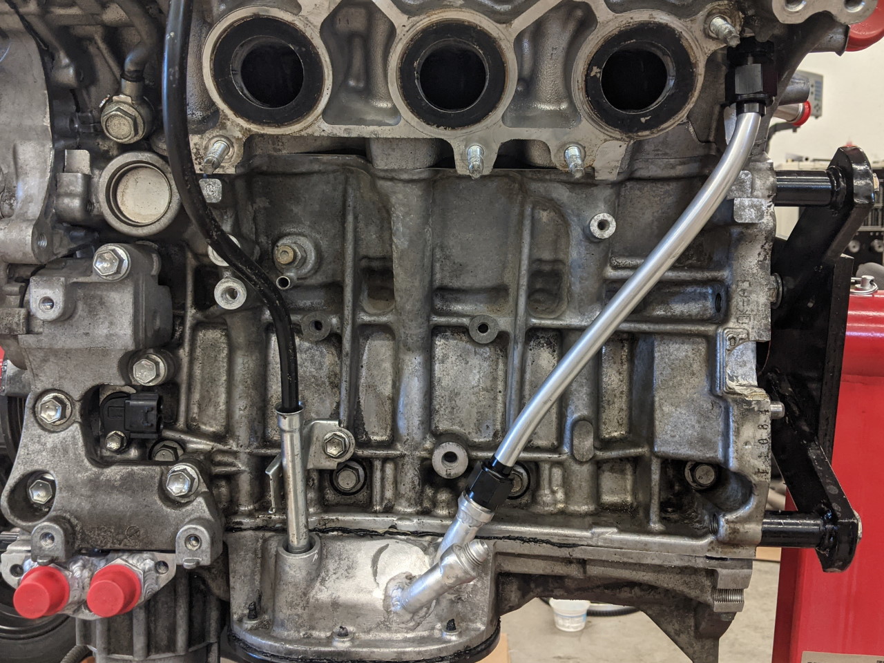
Back to the new external drain on the forward bank, somewhere to attach the drain at the oil pan is needed. The two bent pieces of tube welded to the upper pan were left over from making A/C lines for my 2GR swap. I never throw anything away... The drain line itself is a piece of 1/2" aluminum tube, with 8AN flare nuts installed. It is at an angle of about 60° off of horizontal, which means it should still be slightly "down hill" even at 1.5g lateral. Keep in mind 1g lateral is like tilting the motor at a 45° angle, and higher g forces only increase that! If the tube can't drain while cornering, it won't do much good.
The second drain tube is for my catch can.
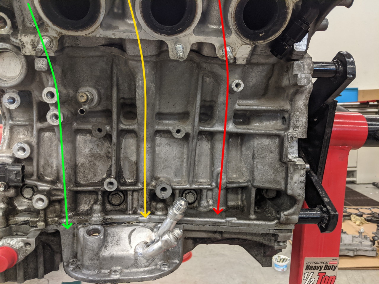
As mentioned previously, part of the problem is that half of the drains on the motor end in the upper pan, far from the pickup in the sump. More than half actually... I have marked below in green the drains that actually go directly to the sump (only one on each bank!), and in red the drains that go back to the upper pan where oil will be "stuck" on RH corners.
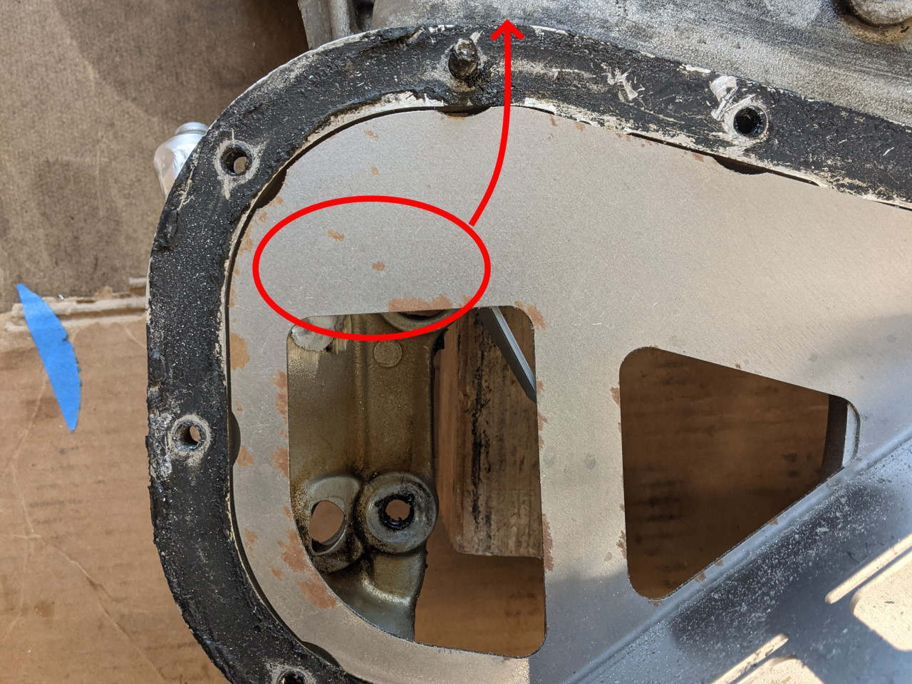
There is also one marked in orange on the front bank. At first glance it appears to hit the sump (just barely). But with a little RH g force applied, and especially once my baffle is installed, oil from this drain will also tend to flow into the upper pan, in the direction of the arrow below. My new drain from the head also exits in this circled area, so if I want it to really help, I need to do something to keep that oil from going back into the upper pan. I designed this small steel plate that installs on one of the upper pans bolts to prevent oil from both the OEM drain and my new drain from going back into the upper pan. This should help keep more oil in the sump where it can do some good.
This small baffle will be an addition to my oil pan baffle kits soon (and available as an add on for those who want to upgrade an existing baffle).
I seriously considered adding an external drain on the rear bank as well to get oil back to the sump instead of the upper pan, but decided against it for complexity and packaging reasons. Maybe the next time I have to take the motor apart... (hopefully, that means never!).
Finally, while I had the motor apart, I took the opportunity to prototype this rubber oil pickup tube. Rather than hovering 1/2" or more off of the bottom of the pan like the stock pickup this gets down to less than 1/4" from the bottom, and the rubber can adjust to take up manufacturing tolerances in this fit. I have not installed it yet as I want to get some data on the effectivity of the drains first, but once I have been able to test it I will offer them for sale if they prove beneficial.
Of course, the ultimate solution to all of this is a dry sump. But have you looked at the cost of dry sump parts?!? Hopefully these measures will help, at a fraction of the cost!

